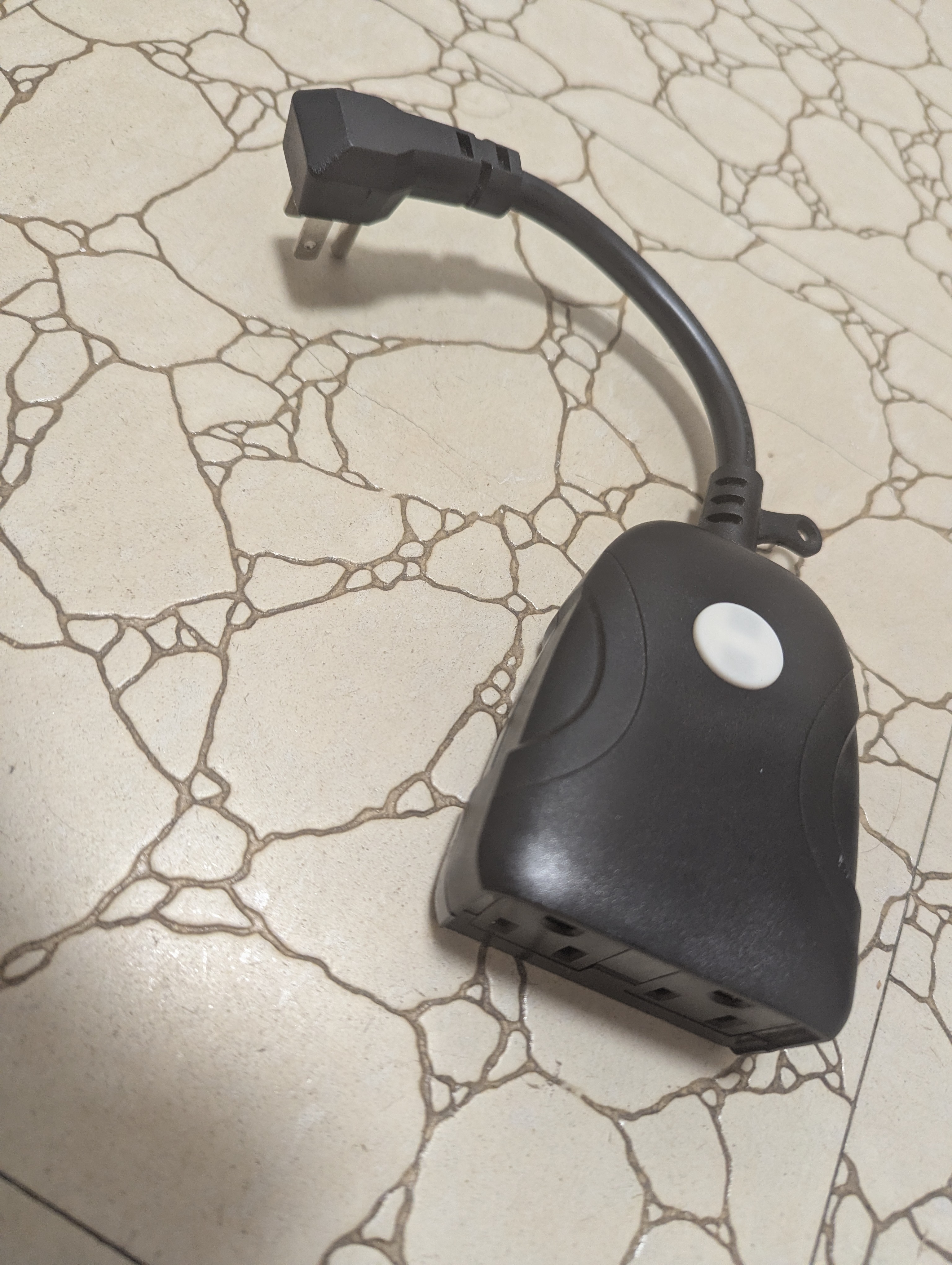
PRIME CCRCWFIO2PK Plug

This smart plug has two outlets controlled by the same relay. The relay is toggled via a button. The blue LED indicates
network connectivity, while the red LED shows the relay state.
The device was purchased at Costco CA.
Model: CCRCWFIO2PK ITM. / ART. No 1221313 FCC ID: 2AMV5-SK509-W-1 Date Code: 08/19
125V AC 60 Hz 15A / 1875W Resistive, 8A / 1000W Tungsten
CHIP: EPS8285
Getting it up and running
USB Serial Converter
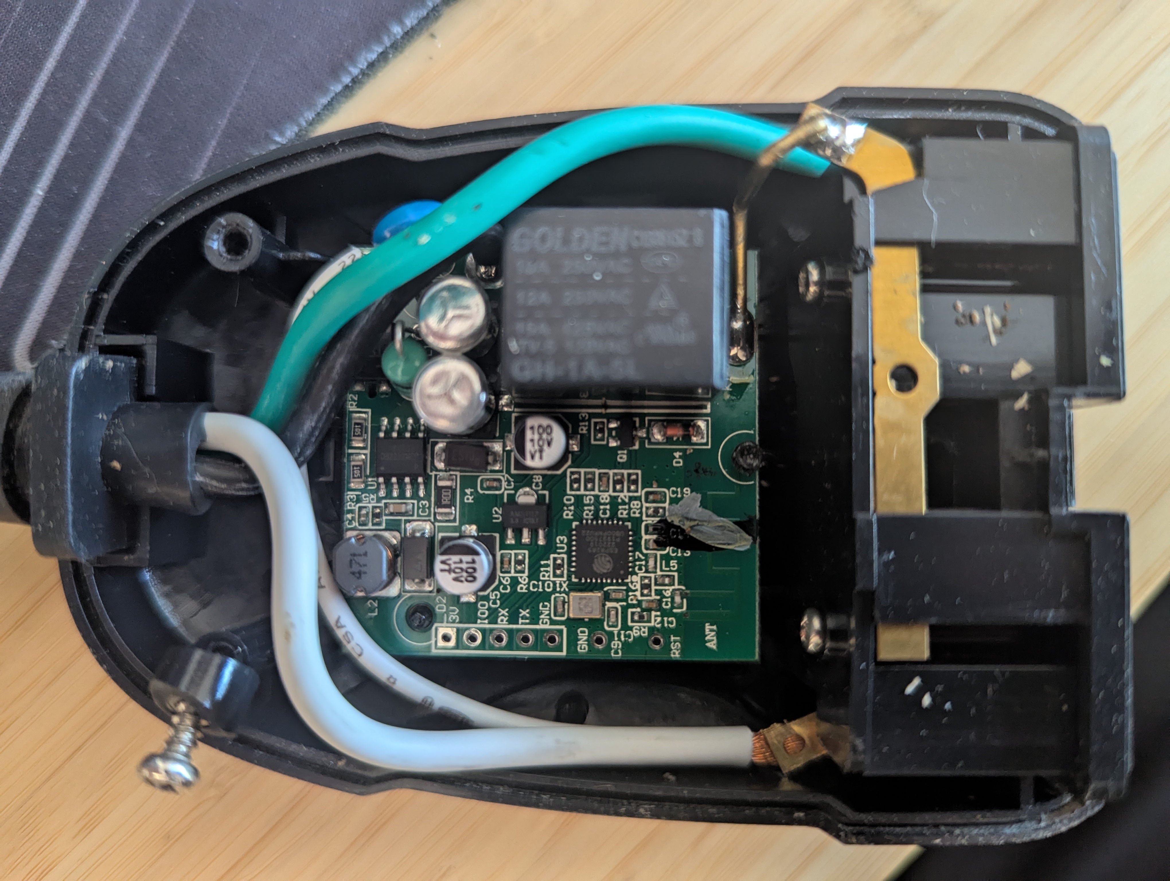
The device must be disassembled to access the UART contacts. There are three screws: two are visible, and the third is
under the sticker in the middle on the opposite side. Once the screws are removed, the lid can be easily taken off.

Connect IO0 to GND to enter boot mode. To restart the device before entering boot mode, either reconnect GND or momentarily connect RST to GND. It is possible to flash the device without soldering the pins, but it may be a bit tricky.
GPIO Pinout
| Pin | Function |
|---|---|
| GPIO04 | Blue LED |
| GPIO05 | Red LED |
| GPIO12 | Relay |
| GPIO13 | Button |
Hardware definition Configuration
substitutions:
  name: ccrwfio2pk
esphome:
  name: "${name}"
  friendly_name: "${name}"
esp8266:
  board: esp8285
logger: null
ota:
  - platform: esphome
    password: !secret ota_password
wifi:
  ssid: wifi_ssid
  password: !secret wifi_password
  ap:
    ssid: "${name} Fallback Hotspot"
    password: !secret ap_password
captive_portal: null
switch:
  - platform: gpio
    name: Blue LED
    inverted: true
    pin:
      number: GPIO4
  - platform: gpio
    name: Red LED
    inverted: true
    pin:
      number: GPIO5
  - platform: gpio
    name: Relay
    pin:
      number: GPIO12
binary_sensor:
  - platform: gpio
    name: Button
    pin:
      number: GPIO13
      mode: INPUT_PULLUP
      inverted: true
Basic Configuration
The following configuration mimics the original behavior: pressing the Button toggles the Relay. The Blue LED
indicates status, and the Red LED turns on when the Relay is on.
substitutions:
  name: ccrwfio2pk
esphome:
  name: "${name}"
  friendly_name: "${name}"
esp8266:
  board: esp8285
logger: null
ota:
  - platform: esphome
    password: !secret ota_password
wifi:
  ssid: !secret wifi_ssid
  password: !secret wifi_password
  ap:
    ssid: "${name} Fallback Hotspot"
    password: !secret ap_password
captive_portal: null
web_server:
  version: 3
status_led:
  pin:
    number: GPIO4
    inverted: true
switch:
  - platform: gpio
    id: relay
    name: Relay
    pin:
      number: GPIO12
    on_turn_on:
      - output.turn_on: red_led
    on_turn_off:
      - output.turn_off: red_led
output:
  - platform: gpio
    id: red_led
    pin:
      number: GPIO5
      inverted: true
binary_sensor:
  - platform: gpio
    name: Button
    pin:
      number: GPIO13
      mode: INPUT_PULLUP
      inverted: true
    on_press:
      then:
        - switch.toggle: relay