Etekcity Voltson ESW01-EU
Flashing
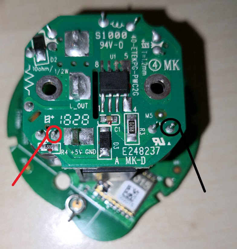
To reach the ESP pins, you need to open the device by unscrewing two (really) small Torx on the front and get the board
out with four Philipps screws.
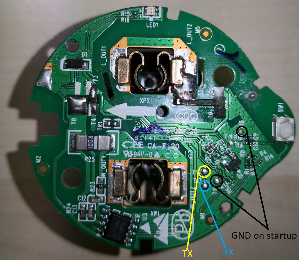
Then, all necessary pads for flashing are accessible. Attach 5V and GND at the bottom, preferably with test hooks.
 For flashing, T12 is TX and T13 is RX. During boot, T11 and T16 pads need to be connected to GND. Easiest is to connect
these pads with pogo pins.

GPIO Pinout
| Pin | Function |
|---|---|
| GPIO4 | Relay |
| GPIO5 | LED blue |
| GPIO12 | HLWBL CF1 Pin |
| GPIO13 | HLW8012 CF Pin |
| GPIO14 | Button |
| GPIO16 | LED yellow |
The HLW8012 SEL pin is permanently pulled high, so you can only read power and voltage. With a small calculation trick
you can get current values though (see current_calculated below).
Basic Configuration
esphome:
  arduino_version: 2.5.1

esp8266:
  board: esp01_1m

wifi:
  ssid: !secret wifi_ssid
  password: !secret wifi_password

status_led:
  pin:
    number: GPIO5

output:
- platform: gpio
  id: led1
  pin: GPIO16

switch:
- platform: gpio
  name: "Relay"
  id: switch1
  pin: GPIO4
  restore_mode: RESTORE_DEFAULT_ON
  on_turn_on:
    - output.turn_on: led1
  on_turn_off:
    - output.turn_off: led1

binary_sensor:
  - platform: gpio
    id: button1
    pin:
      number: GPIO14
      mode: INPUT_PULLUP
      inverted: true
    on_press:
      - switch.toggle: switch1

sensor:
  - platform: hlw8012
    sel_pin: 0   # not connected
    cf_pin: GPIO13
    cf1_pin: GPIO12
    voltage:
      id: voltage
      name: Voltage
    power:
      id: wattage
      name: Wattage
        on_value:
          - sensor.template.publish:
              id: hlw8012_current_calculated
              state: !lambda 'return id(hlw8012_power).state / id(hlw8012_voltage).state;'
    update_interval: 10s
    initial_mode: VOLTAGE
    change_mode_every: 4294967295 # basically never
  - platform: template #disabled
    id: current_calculated
    name: "Current (calculated)"