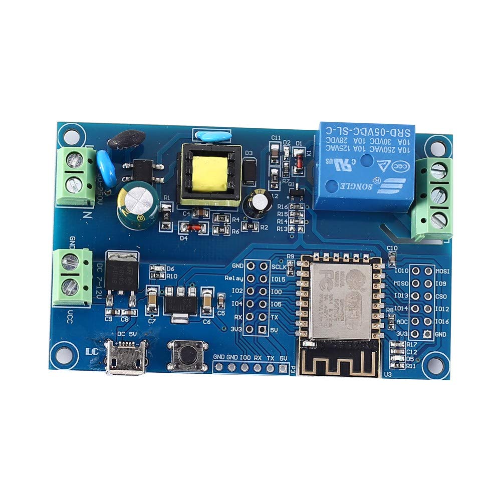
ESP-12F-Relay-X1
Product description
This is a 1-relay board based on ESP-12F, including AC and DC power supplies. It can be found in many online shops.
This might be the original source: http://www.chinalctech.com/m/view.php?aid=472
The relay has COM+NO+NC exposed. Print on relay says it can do 10A at 250VAC.
The board can be powered either via 90-250VAC or via 7-12VDC, or via 5VDC from USB.
All 5V inputs feed the same rail:
- the AC switchmode power supply
- the DC linear regulator
- the Micro-USB port
IMPORTANT: connect only one of the three power inputs at the same time!
The comon 5V rail feeds a 3.3V linear regulator.

GPIO Pinout
This board has headers for every GPIO pin on its ESP-12F.
By default, the relay is connected to GPIO5. If you want to change that, remove R14 and connect the header "Relay" to the desired GPIO.
Programming header:
| Pin | Comment |
|---|---|
| 5V | Could inject +5V from the USB serial-TTL-converter |
| TX | 3.3V level! |
| RX | 3.3V level! |
| GPIO0 | 3.3V level! (pulled up, connect to GND for flashing) |
| GND | |
| GND |
Left header:
| Pin | Comment |
|---|---|
| 5V | 5V rail |
| 3V3 | from onboard voltage regulator |
| TX | 3.3V level! |
| RX | 3.3V level! |
| GPIO5 | drives relay via R14 |
| GPIO4 | |
| GPIO0 | |
| GPIO2 | |
| GPIO15 | |
| Relay | once R14 removed, can be bridged to any GPIO |
| SCLK | |
| GND |
Right header:
| Pin | Comment |
|---|---|
| GND | |
| 3V3 | |
| GPIO16 | connected to red LED |
| ADC | 0V-1V only |
| GPIO12 | |
| GPIO14 | |
| CSO | |
| GPIO13 | |
| GPIO9 | |
| MISO | |
| MOSI | |
| GPIO10 |
Basic Config
esphome:
  name: esp12frelayx1

esp8266:
  board: esp12e

# Use the red LED in the device as a status LED, which will blink if there are warnings (slow) or errors (fast)
status_led:
  pin:
    number: GPIO16
    inverted: True

# relay output, exposed as switch in Home Assistant
switch:
  - platform: gpio
    pin: GPIO5
    name: Relay
    id: relay