TuYa MINI-W1-4CH - PSW-4CH-CBU
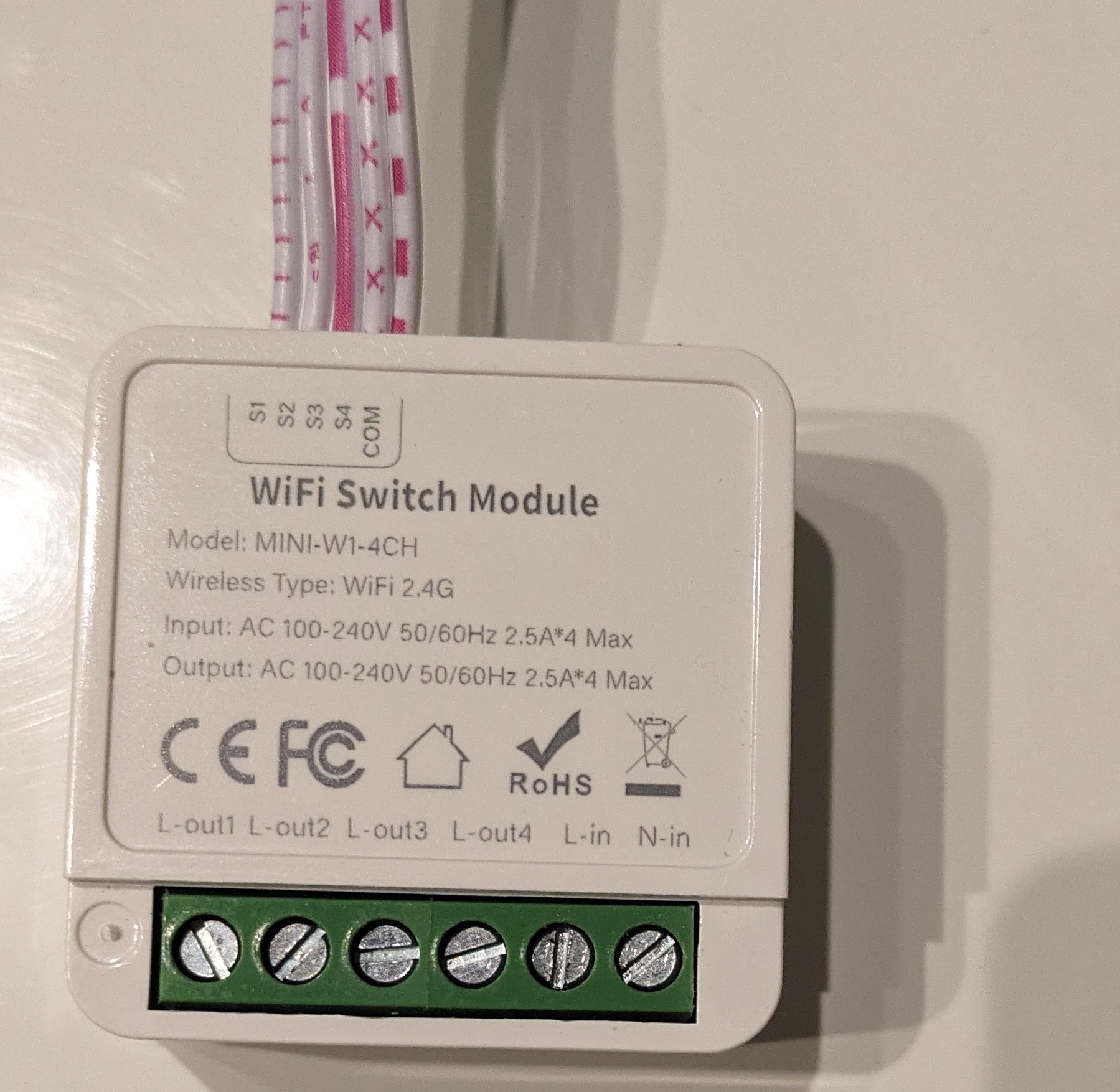
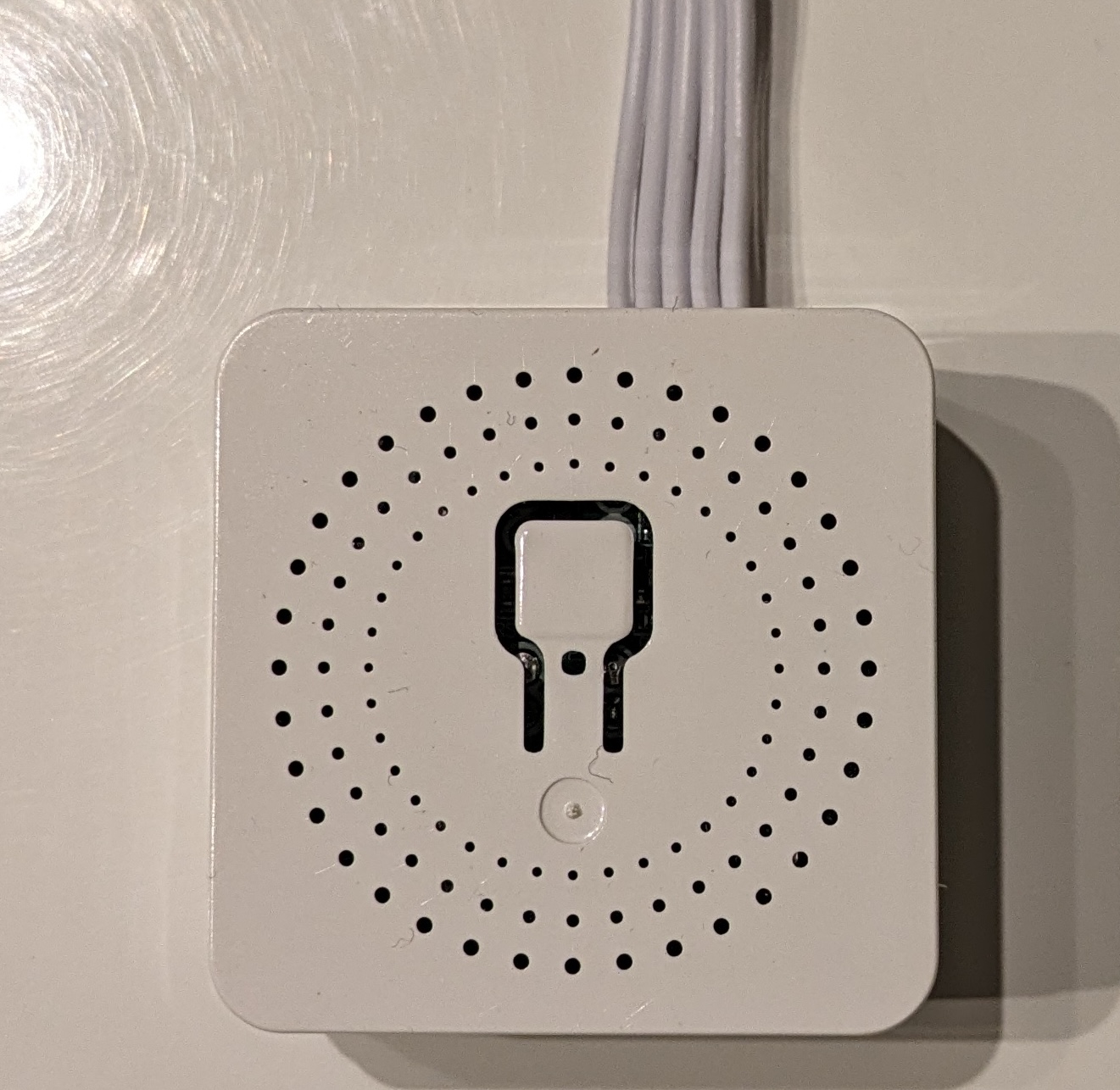
Product Images


Programming
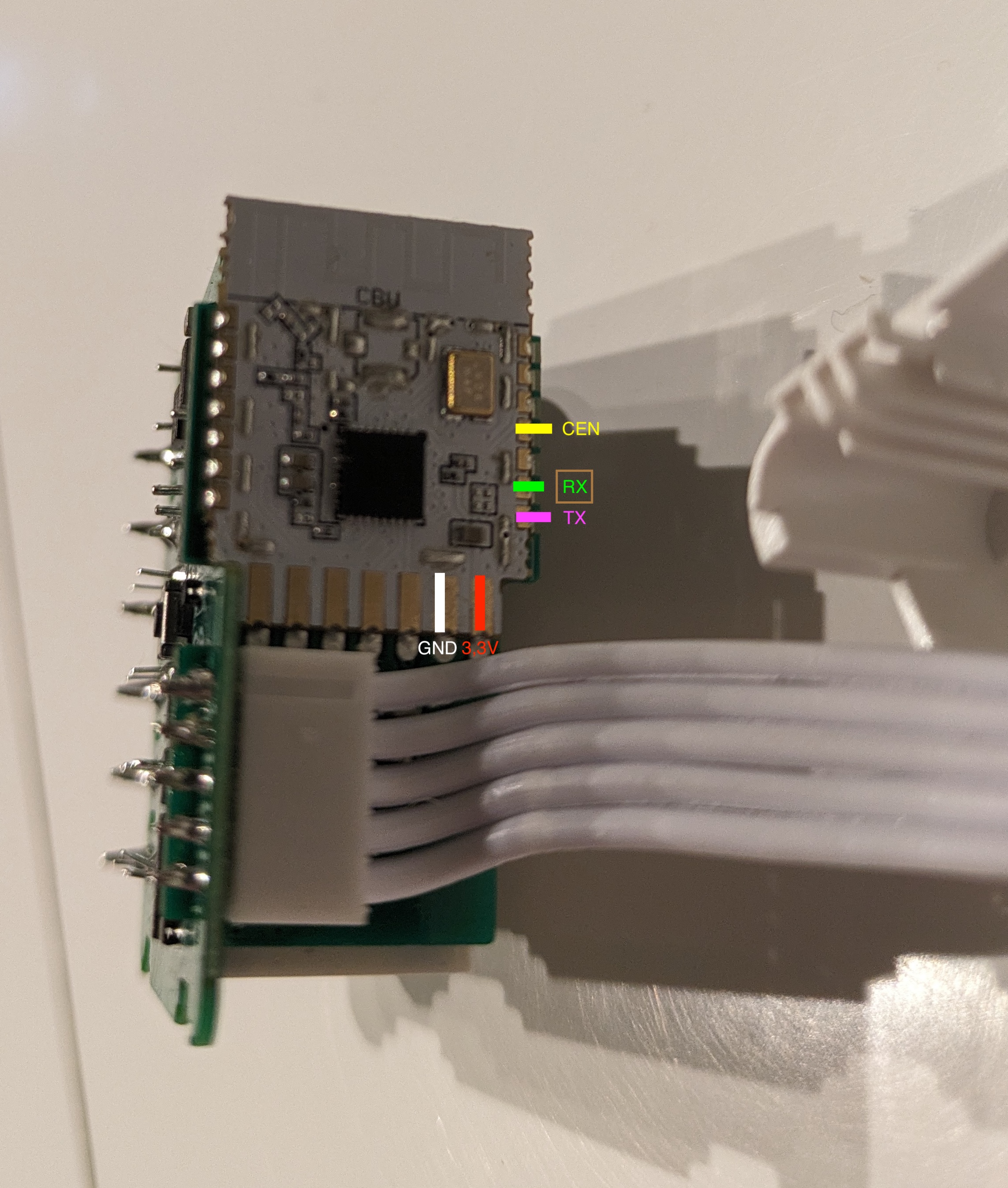
Solder USB TTL wires like below

To enter bootloader mode, ground CEN pin and power device. I used https://github.com/libretiny-eu/ltchiptool to program it
GPIO Pinout
| Pin | Function |
|---|---|
| GPIO23 | Push Button |
| GPIO10 | Relay #1 |
| GPIO24 | Relay #2 |
| GPIO26 | Relay #3 |
| GPIO28 | Relay #4 |
| GPIO11 | Status LED |
| GPIO6 | S1 |
| GPIO7 | S2 |
| GPIO8 | S3 |
| GPIO9 | S4 |
Basic Configuration
substitutions:
  device_name: tuya-wifi-4ch

esphome:
  name: tuya-wifi-4ch
  friendly_name: tuya-wifi-4ch

bk72xx:
  board: cbu

logger:

captive_portal:

status_led:
  pin:
    number: GPIO11
    inverted: yes

output:
  - platform: gpio
    pin: GPIO10
    id: relay1
  - platform: gpio
    pin: GPIO24
    id: relay2
  - platform: gpio
    pin: GPIO26
    id: relay3
  - platform: gpio
    pin: GPIO28
    id: relay4

light:
  - platform: binary
    name: "Relay 1"
    output: relay1
    id: sw1
  - platform: binary
    name: "Relay 2"
    output: relay2
    id: sw2
  - platform: binary
    name: "Relay 3"
    output: relay3
    id: sw3
  - platform: binary
    name: "Relay 4"
    output: relay4
    id: sw4

binary_sensor:
  - platform: gpio
    internal: true
    pin:
      number: GPIO6
      mode:
        input: true
        pullup: true
      inverted: true
    name: "S1"
    on_press:
      - light.toggle: sw1
  - platform: gpio
    internal: true
    pin:
      number: GPIO7
      mode:
        input: true
        pullup: true
      inverted: true
    name: "S2"
    on_press:
      - light.toggle: sw2
  - platform: gpio
    internal: true
    pin:
      number: GPIO8
      mode:
        input: true
        pullup: true
      inverted: true
    name: "S3"
    on_press:
      - light.toggle: sw3
  - platform: gpio
    internal: true
    pin:
      number: GPIO9
      mode:
        input: true
        pullup: true
      inverted: true
    name: "S4"
    on_press:
      - light.toggle: sw4
  - platform: gpio
    internal: true
    pin:
      number: GPIO23
      mode:
        input: true
        pullup: true
      inverted: true
    name: "Push Button"