Shelly Pro 2
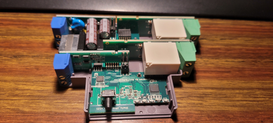
Information about the pinout and internals of the Shelly Pro 2.
It's the same board as the Shelly Pro 1. The only difference is the addition of a second relay.
Pinout
| ESP32 DOWDQ6 | Component |
|---|---|
| GPIO 4 | SN74HC595B SPI CS |
| GPIO 12 | SPI MISO |
| GPIO 13 | SPI MOSI |
| GPIO 14 | SPI CLK |
| GPIO 17 | LAN8720A CLKIN |
| GPIO 18 | LAN8720A MDIO |
| GPIO 19 | LAN8720A TXD0 |
| GPIO 21 | LAN8720A TXEN |
| GPIO 22 | LAN8720A TXD1 |
| GPIO 23 | LAN8720A MDC |
| GPIO 25 | LAN8720A RXD0 |
| GPIO 26 | LAN8720A RXD1 |
| GPIO 27 | LAN8720A CRS_DV |
| GPIO 35 | Reset Button |
| GPIO 36 | ADC Temperature 1 |
| GPIO 37 | ADC Temperature 2 |
| GPIO 38 | Switch input 1 |
| GPIO 39 | Switch input 2 |
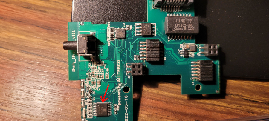
Shift register
A shift register is controlling the WIFI RGB LEDs and the 2 relays.
| SN74HC595B | Component |
|---|---|
| QA | Relay 1 + Out 1 LED |
| QB | Relay 2 + Out 2 LED |
| QC | WIFI RGB LED (Blue) |
| QD | WIFI RGB LED (Green) |
| QE | WIFI RGB LED (Red) |
| QF | NC |
| QG | NC |
| QH | NC |
The Out 1 status LED and the relay 1 are on the same output. The same is true for the Out 2 status LED and the relay 2. Turning on the relay turns the corresponding LED on.
The WIFI LED is an RGB LED. By turning each component on or off, you have access to 8 configurations:
| R | G | B | Color |
|---|---|---|---|
| 0 | 0 | 0 | OFF |
| 0 | 0 | 1 | Blue |
| 0 | 1 | 0 | Green |
| 0 | 1 | 1 | Cyan |
| 1 | 0 | 0 | Red |
| 1 | 0 | 1 | Magenta |
| 1 | 1 | 0 | Yellow |
| 1 | 1 | 1 | White |
Programming Pinout

Note that the pin pitch is 1.27mm, so standard 2.54mm Dupont cables won't work.
Basic Configuration
esphome:
  name: shelly-pro-2

esp32:
  variant: esp32
  framework:
    type: arduino


logger:

api:

ota:
  platform: esphome

wifi:
  ssid: !secret wifi_ssid
  password: !secret wifi_password
  ap:
    ssid: "Shelly-Pro-2"
    password: "BzwFc7HsRihG"

# ethernet:
#   type: LAN8720
#   mdc_pin: GPIO23
#   mdio_pin: GPIO18
#   clk_mode: GPIO17_OUT


captive_portal:

spi:
  clk_pin: GPIO14
  mosi_pin: GPIO13
  miso_pin:
    number: GPIO12
    ignore_strapping_warning: true

button:
  - platform: shutdown
    id: do_shutdown
  - platform: restart
    name: "Restart"
    id: do_restart

binary_sensor:
  - platform: gpio
    id: reset_button
    pin:
      number: 35
      inverted: true
    on_release:
      then:
        button.press: do_restart

  - platform: gpio
    id: input1
    pin:
      number: 38
    on_press:
      then:
        switch.toggle: relay1

  - platform: gpio
    id: input2
    pin:
      number: 39
    on_press:
      then:
        switch.toggle: relay2

sensor:
  - platform: adc
    id: temp_voltage1
    pin: GPIO36
    attenuation: auto
  - platform: resistance
    id: temp_resistance1
    sensor: temp_voltage1
    configuration: DOWNSTREAM
    resistor: 10kOhm
  - platform: ntc
    sensor: temp_resistance1
    name: Temperature 1
    unit_of_measurement: "°C"
    accuracy_decimals: 1
    icon: "mdi:thermometer"
    calibration:
      b_constant: 3350
      reference_resistance: 10kOhm
      reference_temperature: 298.15K
    on_value_range:
      - above: 90
        then:
          - switch.turn_off: relay1
          - switch.turn_off: relay2
          - button.press: do_shutdown

  - platform: adc
    id: temp_voltage2
    pin: GPIO37
    attenuation: auto
  - platform: resistance
    id: temp_resistance2
    sensor: temp_voltage2
    configuration: DOWNSTREAM
    resistor: 10kOhm
  - platform: ntc
    sensor: temp_resistance2
    name: Temperature 2
    unit_of_measurement: "°C"
    accuracy_decimals: 1
    icon: "mdi:thermometer"
    calibration:
      b_constant: 3350
      reference_resistance: 10kOhm
      reference_temperature: 298.15K
    on_value_range:
      - above: 90
        then:
          - switch.turn_off: relay1
          - switch.turn_off: relay2
          - button.press: do_shutdown

sn74hc595:
  - id: 'sn74hc595_hub'
    type: spi
    latch_pin: GPIO4
    sr_count: 1

switch:
  - platform: gpio
    name: "Relay 1"
    id: relay1
    pin:
      sn74hc595: sn74hc595_hub
      number: 0
      inverted: false

  - platform: gpio
    name: "Relay 2"
    id: relay2
    pin:
      sn74hc595: sn74hc595_hub
      number: 1
      inverted: false

  - platform: gpio
    id: wifi_led_blue
    pin:
      sn74hc595: sn74hc595_hub
      number: 2
      inverted: true

  - platform: gpio
    id: wifi_led_green
    pin:
      sn74hc595: sn74hc595_hub
      number: 3
      inverted: true

  - platform: gpio
    id: wifi_led_red
    pin:
      sn74hc595: sn74hc595_hub
      number: 4
      inverted: true