IWOOLE Table Lamp
The IWOOLE Table Lamp is a RGBW lamp normally configured using the Tuya Smart App. It is available from various retailers online or directly from iwoole.com.
Device overview
Note
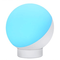
The following information relates to the desk model depicted above. A free-standing version and a desk version with a longer arm are available. They are likely to share the same internals and configuration, but I can not be certain.
My device had no external markings at all.
The device is a basic 4-channel PWM RGBW light in a simple elegant housing. The LEDs are not individually addressable. No other sensors, outputs or status LEDs are available.
The MOSFETs for the different color channels are connected as follows:
- GPIO04: White
- GPIO12: Green
- GPIO13: Blue
- GPIO14: Red
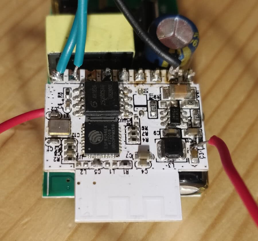
Internal markings
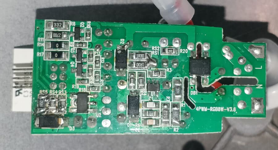
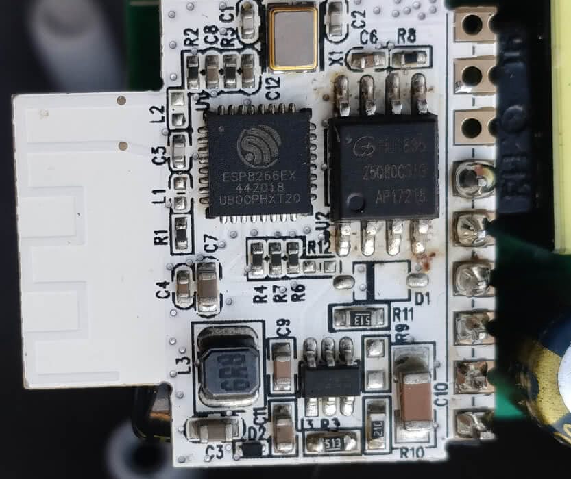
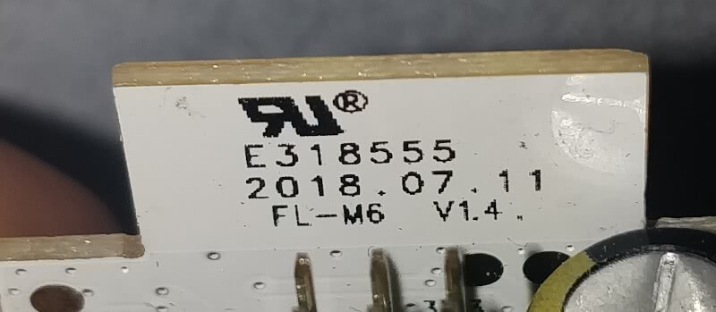
ESPHome configuration
Since there is only one RGBW light to configure the .yaml file is fairly
straightforward. Alternatively, you could configure each channel as a
separate light if desired. I prefer to use the rgbw_color_interlock
option along with the configuration below.
Example configuration
esphome:
  name: "IWOOLE Table Lamp"
  #ESP type is ESP8266EX with 1MB flash

esp8266:
  board: esp01_1m

# Insert wifi and api configuration here

# Configuration for IWOOLE PWM light
light:
  - platform: rgbw
    name: "Light"
    red: output_red
    green: output_green
    blue: output_blue
    white: output_white

output:
  - platform: esp8266_pwm
    id: output_red
    pin: GPIO14
  - platform: esp8266_pwm
    id: output_green
    pin: GPIO12
  - platform: esp8266_pwm
    id: output_blue
    pin: GPIO13
  - platform: esp8266_pwm
    id: output_white
    pin: GPIO4
Flashing
Warning
The circuit inside will be exposed to mains voltage. Do not connect your device to the mains when flashing.
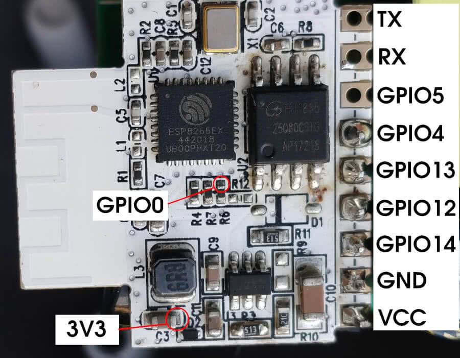
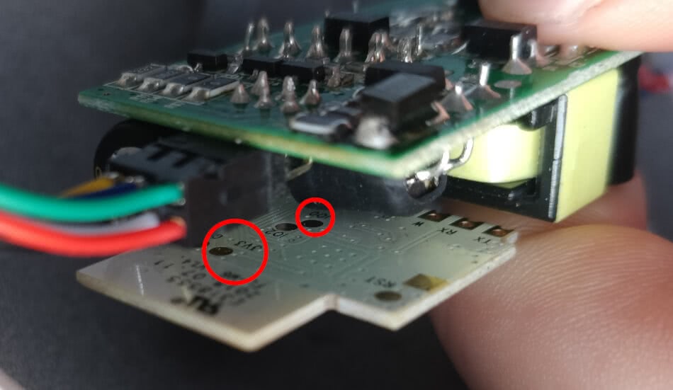
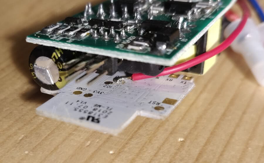
There are pads available for 3V3 and GPIO0 on the back. I have tried to find easier solder points on the front, marked in the image above. Be aware that the pin labeled VCC does not carry 3V3, but 24V DC. If, for any reason, you wanted to connect any other sensor or component, the exposed pin for GPIO5 can be used, in addition to RX (GPIO3) and TX (GPIO1).
Ensure GPIO0 is connected to ground to get the device into programming mode, but also don't forget to disconnect this when you expect the device to start in normal mode.
