SMARTBOB SM-LITE-1616R
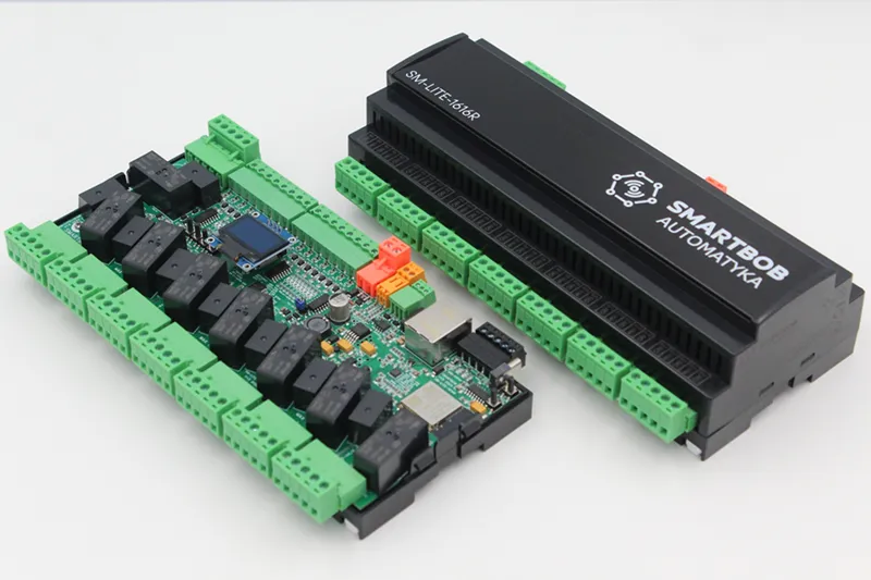
SMARTBOB devices are a series of smart-home controllers designed for open home automation. They are based on ESP32 controllers and offer various useful options.
The product is dedicated to controlling AC and DC circuits (without power regulation, on/off), such as lights, power supplies, blinds, valves, sockets, and relays, as well as control signals for gate control and alarms
Available pre-flashed with ESPHome or SUPLA.
Maker: https://smartbob.pl
Product page: https://smartbob.pl/pl/lite-1-poziom/3-sm-lite-1616r.html
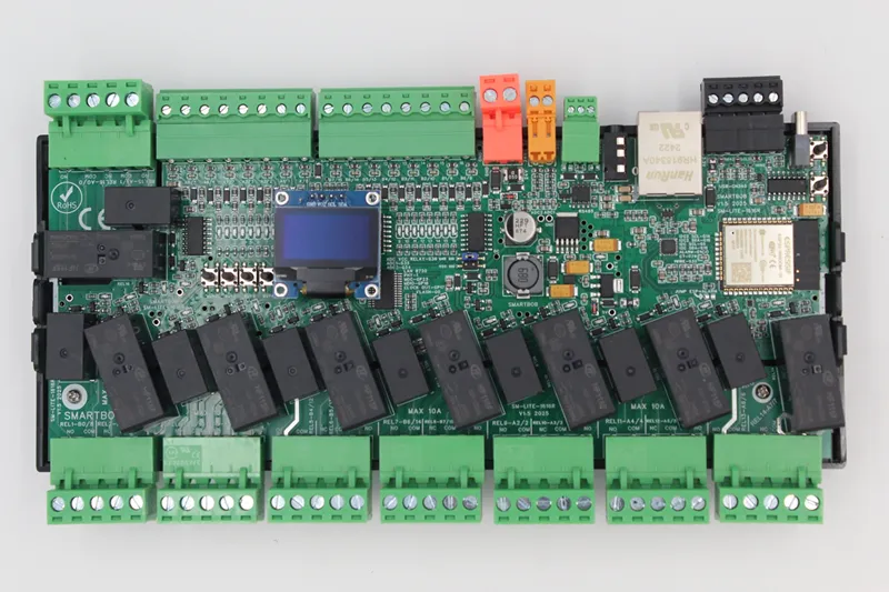
SM-LITE-1616R V1.5 version basic description
- 24V DC power supply (max 0.5A)
- 16 input, VCC or GND logic level (by MCP23017 expander)
- 16 output by 10A relays, potential-free with the possibility of roller shutter interlock (by MCP23017 expander)
- 2x ADC for up to 24V voltage measurement (or input)
- 1x ADC for power supply voltage measurement
- Additional communication by: 2x I2C, 1WIRE, RS485
- CT clamp input for SCT clamps
- LAN or WIFI communication
- 0.96C OLED display
- Integrated USB programmer
- Integrated hardware over-temp protection by 2xTMP102 (all relay off, hardware 80C or lower defined in YAML)
- Integrated input control test buttons
GPIO Pinout for V1.5 version
LAN7820
Can be used for ethernet 10/100Mb communication.
| Pin | Function |
|---|---|
| TYPE | LAN7820 |
| GPIO23 | MDC |
| GPIO18 | MDIO |
| GPIO17 | CLOCK OUT |
| GPIO25 | RX DO |
| GPIO26 | RX D1 |
| GPIO27 | CRS |
| GPIO19 | TX D0 |
| GPIO22 | TX D1 |
| GPIO21 | TX EN |
| PHY | 1 |
I2C
Contains two I2C data lines :
- I2C 1 internal for MCP23017 expanders and OLED (reference speed 400kHz)
- I2C 2 for external sensors or as input (3.3V logic level). Can be used to read external I2C
- sensor like SHT31 or as input (3.3V logic level). Integrated 2.3k Ohm pull up on all lines.
| Pin | Function |
|---|---|
| GPIO15 | SDA 1 internal |
| GPIO5 | SCL 1 internal |
| GPIO16 | SDA 2 external |
| GPIO14 | SDA 2 external |
Board contain this devices on internal I2C 1 line:
| Address | Device |
|---|---|
| 0x20 | MCP23017 IN |
| 0x21 | MCP23017 OUT |
| 0x3C | OLED |
| 0x48 | TMP102 1 |
| 0x49 | TMP102 2 |
RS485
Can be used to read external modbus devices like power meter like Eastron SDM120/240/630.
| Pin | Function |
|---|---|
| GPIO13 | RX |
| GPIO33 | TX |
1WIRE
Can be used to read external sensor by 1WIRE like. DS18B20 or as input (3.3V logic level). Integrated 2.3k Ohm pull up.
| Pin | Function |
|---|---|
| GPIO32 | 1WIRE |
ADC or additional input
ADC1, ADC2 can be used to read ADC voltage up to 24V or use as input (24V logic level). One ADC3 is connected to power connector to measure voltage connected to board.
| Pin | Function |
|---|---|
| GPIO35 | External ADC1 or INPUT |
| GPIO34 | External ADC2 or INPUT |
| GPIO36 | Internal ADC3 |
Integrated divider with calibration values for ADC1-2:
| Adc | Voltage |
|---|---|
| 0.62 | 5 |
| 1.22 | 10 |
| 1.83 | 15 |
| 2.425 | 20 |
| 2.975 | 25 |
Integrated divider with calibration values for ADC3:
| Adc | Voltage |
|---|---|
| 0.55 | 10 |
| 0.825 | 15 |
| 1.10 | 20 |
| 1.37 | 25 |
CT current clamp sensor input
Can be used to read from SCT-013 witch xA/1V output.
| Pin | Function |
|---|---|
| GPIO39 | CT_CLAMP |
Example YAML:
substitutions:  name: sm-lite-1616r-v15  friendly_name: sm-lite-1616r-v15
# NAMEesphome:  name: ${name}  comment: ${friendly_name}  on_boot:    then:      - display.page.show: page1      - delay: 7s      - display.page.show: page2
# HAapi:  encryption:    key: "xxxxxxxxxxxxxxxxxxxxxxxxxxxxxxx"  reboot_timeout: 0s
# OTAota:  - platform: esphome  #password: "xxxxxxxxxxxxxxxxxxxxxxxxxxxxxxx"
# PROCESOResp32:  variant: esp32  framework:    type: arduino
# LOGOWANIElogger:  level: DEBUG
# 1WIREone_wire:  - platform: gpio    pin: GPIO32
# UART-RS485uart:  - id: mod_uart    rx_pin: 13    tx_pin: 33    baud_rate: 9600    stop_bits: 1    data_bits: 8    parity: NONE    debug:      direction: BOTH
# SENSOR CONFIGURATIONsensor:  # SCT SENSOR  - platform: ct_clamp    sensor: adc_ct    name: "SCT Current"    update_interval: 1s    filters:      - calibrate_linear:        - 0 -> 0        - 0.1 -> 2.5
  # SCT ADC  - platform: adc    pin: GPIO39    id: adc_ct    attenuation: 11db
  # EXT ADC INPUT 2  - platform: adc    pin: GPIO34    id: adc_sensor_2    attenuation: 11db    name: "Voltage ADC 2"    device_class: "voltage"    filters:      - calibrate_linear:        - 0.62 -> 5        - 1.22 -> 10        - 1.83 -> 15        - 2.425 -> 20        - 2.975 -> 25    update_interval: 1s
  # EXT ADC INPUT 1  - platform: adc    pin: GPIO35    id: adc_sensor_1    attenuation: 11db    name: "Voltage ADC 1"    device_class: "voltage"    filters:      - calibrate_linear:        - 0.62 -> 5        - 1.22 -> 10        - 1.83 -> 15        - 2.425 -> 20        - 2.975 -> 25    update_interval: 1s
  # ADC INPUT VOLTAGE CHANNEL  - platform: adc    pin: GPIO36    id: adc_sensor_4    attenuation: 11db    name: "Power voltage"    device_class: "voltage"    filters:      - calibrate_linear:        - 0.55 -> 10        - 0.825 -> 15        - 1.10 -> 20        - 1.37 -> 25    update_interval: 1s
  # TMP102  - platform: tmp102    i2c_id: bus_a    name: "Temperatura PCB 1"    address: 0x48    id: temp_1    update_interval: 8s    on_value:      if:        condition:          sensor.in_range:            id: temp_1            above: 70.0        then:        - display.page.show: page3        - switch.turn_off: relay_01        - switch.turn_off: relay_02        - switch.turn_off: relay_03        - switch.turn_off: relay_04        - switch.turn_off: relay_05        - switch.turn_off: relay_06        - switch.turn_off: relay_07        - switch.turn_off: relay_08        - switch.turn_off: relay_09        - switch.turn_off: relay_10        - switch.turn_off: relay_11        - switch.turn_off: relay_12        - switch.turn_off: relay_13        - switch.turn_off: relay_14        - switch.turn_off: relay_15        - switch.turn_off: relay_16
  # TMP102  - platform: tmp102    i2c_id: bus_a    name: "Temperatura PCB 2"    address: 0x49    id: temp_2    update_interval: 8s    on_value:      if:        condition:          sensor.in_range:            id: temp_2            above: 70.0        then:        - display.page.show: page3        - switch.turn_off: relay_01        - switch.turn_off: relay_02        - switch.turn_off: relay_03        - switch.turn_off: relay_04        - switch.turn_off: relay_05        - switch.turn_off: relay_06        - switch.turn_off: relay_07        - switch.turn_off: relay_08        - switch.turn_off: relay_09        - switch.turn_off: relay_10        - switch.turn_off: relay_11        - switch.turn_off: relay_12        - switch.turn_off: relay_13        - switch.turn_off: relay_14        - switch.turn_off: relay_15        - switch.turn_off: relay_16
  # TIME  - platform: uptime    name: Uptime Sensor    id: uptime_sensor_M03    internal: true    update_interval: 60s    on_raw_value:      then:        - text_sensor.template.publish:            id: uptime_human_M03            state: !lambda |-              int seconds = round(id(uptime_sensor_M03).raw_state);              int days = seconds / (24 * 3600);              seconds = seconds % (24 * 3600);              int hours = seconds / 3600;              seconds = seconds % 3600;              int minutes = seconds /  60;              seconds = seconds % 60;              return (                (days ? to_string(days) + "d " : "") +                (hours ? to_string(hours) + "h " : "") +                (minutes ? to_string(minutes) + "m " : "") +                (to_string(seconds) + "s")              ).c_str();
  # UPTIME  - platform: uptime    name: "Uptime Sensor M03"    id: upt_M03    internal: true
# KONFIGRUACJA ZEGARA CZASU RZECZYWISTEGOtime:  - platform: homeassistant    id: homeassistant_time  - platform: sntp    id: sntp_time    timezone: Europe/Sofia    servers:     - 0.pool.ntp.org     - 1.pool.ntp.org     - 2.pool.ntp.org
# LAN OR WIFI#wifi:  #ssid: "MY_WIFI_XX"  #password: "MY_WIFI_XX"  #id: eth
ethernet:  type: LAN8720  mdc_pin: GPIO23  mdio_pin: GPIO18  clk_mode: GPIO17_OUT  phy_addr: 1  id: eth
  #manual_ip:  #  static_ip: 192.168.0.50  #  gateway: 192.168.0.1  #  subnet: 255.255.255.0  #  dns1 : 8.8.8.8  #  dns2 : 8.8.4.4

# I2Ci2c:   - id: bus_a     sda: 15     scl: 5     scan: true     frequency: 400kHz   - id: bus_b     sda: 16     scl: 14     scan: true     frequency: 400kHz
# MCP23017mcp23017:  - id: 'mcp23017_hub_2'    address: 0x20    i2c_id: bus_a  - id: 'mcp23017_hub_1'    address: 0x21    i2c_id: bus_a
# OUTPUTSswitch:  - platform: gpio    name: "REALY-01"    id: relay_01    pin:      mcp23xxx: mcp23017_hub_1      number: 8      mode: OUTPUT      inverted: false  - platform: gpio    name: "REALY-02"    id: relay_02    pin:      mcp23xxx: mcp23017_hub_1      number: 9      mode: OUTPUT      inverted: false  - platform: gpio    name: "REALY-03"    id: relay_03    pin:      mcp23xxx: mcp23017_hub_1      number: 10      mode: OUTPUT      inverted: false  - platform: gpio    name: "REALY-04"    id: relay_04    pin:      mcp23xxx: mcp23017_hub_1      number: 11      mode: OUTPUT      inverted: false  - platform: gpio    name: "REALY-05"    id: relay_05    pin:      mcp23xxx: mcp23017_hub_1      number: 12      mode: OUTPUT      inverted: false  - platform: gpio    name: "REALY-06"    id: relay_06    pin:      mcp23xxx: mcp23017_hub_1      number: 13      mode: OUTPUT      inverted: false  - platform: gpio    name: "REALY-07"    id: relay_07    pin:      mcp23xxx: mcp23017_hub_1      number: 14      mode: OUTPUT      inverted: false  - platform: gpio    name: "REALY-08"    id: relay_08    pin:      mcp23xxx: mcp23017_hub_1      number: 15      mode: OUTPUT      inverted: false  - platform: gpio    name: "REALY-09"    id: relay_09    pin:      mcp23xxx: mcp23017_hub_1      number: 2      mode: OUTPUT      inverted: false  - platform: gpio    name: "REALY-10"    id: relay_10    pin:      mcp23xxx: mcp23017_hub_1      number: 3      mode: OUTPUT      inverted: false  - platform: gpio    name: "REALY-11"    id: relay_11    pin:      mcp23xxx: mcp23017_hub_1      number: 4      mode: OUTPUT      inverted: false  - platform: gpio    name: "REALY-12"    id: relay_12    pin:      mcp23xxx: mcp23017_hub_1      number: 5      mode: OUTPUT      inverted: false  - platform: gpio    name: "REALY-13"    id: relay_13    pin:      mcp23xxx: mcp23017_hub_1      number: 6      mode: OUTPUT      inverted: false  - platform: gpio    name: "REALY-14"    id: relay_14    pin:      mcp23xxx: mcp23017_hub_1      number: 7      mode: OUTPUT      inverted: false  - platform: gpio    name: "REALY-15"    id: relay_15    pin:      mcp23xxx: mcp23017_hub_1      number: 1      mode: OUTPUT      inverted: false  - platform: gpio    name: "REALY-16"    id: relay_16    pin:      mcp23xxx: mcp23017_hub_1      number: 0      mode: OUTPUT      inverted: false
# INPUTSbinary_sensor:  - platform: gpio    name: "INPUT-01"    id: input_01    pin:      mcp23xxx: mcp23017_hub_2      number: 4      mode:        input: true        pullup: false      inverted: true    filters:    - delayed_on: 30ms    on_press:       then:        - switch.toggle: relay_01  - platform: gpio    name: "INPUT-02"    id: input_02    pin:      mcp23xxx: mcp23017_hub_2      number: 5      mode:        input: true        pullup: false      inverted: true    filters:    - delayed_on: 30ms    on_press:       then:        - switch.toggle: relay_02  - platform: gpio    name: "INPUT-03"    id: input_03    pin:      mcp23xxx: mcp23017_hub_2      number: 6      mode:        input: true        pullup: false      inverted: true    filters:    - delayed_on: 30ms    on_press:       then:        - switch.toggle: relay_03  - platform: gpio    name: "INPUT-04"    id: input_04    pin:      mcp23xxx: mcp23017_hub_2      number: 7      mode:        input: true        pullup: false      inverted: true    filters:    - delayed_on: 30ms    on_press:       then:        - switch.toggle: relay_04  - platform: gpio    name: "INPUT-05"    id: input_05    pin:      mcp23xxx: mcp23017_hub_2      number: 3      mode:        input: true        pullup: false      inverted: true    filters:    - delayed_on: 30ms    on_press:       then:        - switch.toggle: relay_05  - platform: gpio    name: "INPUT-06"    id: input_06    pin:      mcp23xxx: mcp23017_hub_2      number: 2      mode:        input: true        pullup: false      inverted: true    filters:    - delayed_on: 30ms    on_press:       then:        - switch.toggle: relay_06  - platform: gpio    name: "INPUT-07"    id: input_07    pin:      mcp23xxx: mcp23017_hub_2      number: 1      mode:        input: true        pullup: false      inverted: true    filters:    - delayed_on: 30ms    on_press:       then:        - switch.toggle: relay_07  - platform: gpio    name: "INPUT-08"    id: input_08    pin:      mcp23xxx: mcp23017_hub_2      number: 0      mode:        input: true        pullup: false      inverted: true    filters:    - delayed_on: 30ms    on_press:       then:        - switch.toggle: relay_08  - platform: gpio    name: "INPUT-09"    id: input_09    pin:      mcp23xxx: mcp23017_hub_2      number: 15      mode:        input: true        pullup: false      inverted: true    filters:    - delayed_on: 30ms    on_press:       then:        - switch.toggle: relay_09  - platform: gpio    name: "INPUT-10"    id: input_10    pin:      mcp23xxx: mcp23017_hub_2      number: 14      mode:        input: true        pullup: false      inverted: true    filters:    - delayed_on: 30ms    on_press:       then:        - switch.toggle: relay_10  - platform: gpio    name: "INPUT-11"    id: input_11    pin:      mcp23xxx: mcp23017_hub_2      number: 13      mode:        input: true        pullup: false      inverted: true    filters:    - delayed_on: 30ms    on_press:       then:        - switch.toggle: relay_11  - platform: gpio    name: "INPUT-12"    id: input_12    pin:      mcp23xxx: mcp23017_hub_2      number: 12      mode:        input: true        pullup: false      inverted: true    filters:    - delayed_on: 30ms    on_press:       then:        - switch.toggle: relay_12  - platform: gpio    name: "INPUT-13"    id: input_13    pin:      mcp23xxx: mcp23017_hub_2      number: 11      mode:        input: true        pullup: false      inverted: true    filters:    - delayed_on: 30ms    on_press:       then:        - switch.toggle: relay_13  - platform: gpio    name: "INPUT-14"    id: input_14    pin:      mcp23xxx: mcp23017_hub_2      number: 10      mode:        input: true        pullup: false      inverted: true    filters:    - delayed_on: 30ms    on_press:       then:        - switch.toggle: relay_14  - platform: gpio    name: "INPUT-15"    id: input_15    pin:      mcp23xxx: mcp23017_hub_2      number: 9      mode:        input: true        pullup: false      inverted: true    filters:    - delayed_on: 30ms    on_press:       then:        - switch.toggle: relay_15  - platform: gpio    name: "INPUT-16"    id: input_16    pin:      mcp23xxx: mcp23017_hub_2      number: 8      mode:        input: true        pullup: false      inverted: true    filters:    - delayed_on: 30ms    on_press:       then:        - switch.toggle: relay_16


# WEB SERWERweb_server:  port: 80
# TEXTtext_sensor:  - platform: template    name: "ESP32-M03 Uptime"    id: uptime_human_M03    icon: mdi:clock-start  - platform: template    name: "IP"    id: ip_address    entity_category: diagnostic    icon: "mdi:ip-network"    #lambda: return { id(eth).get_ip_address().str() };    lambda: return { id(eth).get_ip_addresses()[0].str() };    update_interval: 10s
# FONTfont:- file: "gfonts://Roboto"  id: font1  size: 12
# DISPLAYdisplay:  - platform: ssd1306_i2c    i2c_id: bus_a    model: "SSD1306_128X64"    id: oled_display    pages:      - id: page1        lambda: |-          it.printf(32, 5, id(font1), "SMARTBOB");          it.printf(27, 22, id(font1), "AUTOMATYKA");          it.printf(5, 39, id(font1), "WWW.SMARTBOB.PL");      - id: page2        lambda: |-          int seconds = round(id(upt_M03).state);          int days = seconds / (24 * 3600);          seconds = seconds % (24 * 3600);          int hours = seconds / 3600;          it.printf(1, 1,  id(font1), "%s", id(ip_address).state.c_str());          it.printf(1, 17, id(font1),"%d dni, %02d godzin",days,hours);          it.printf(1, 33, id(font1), "SM-LITE-1616R");          it.printf(1, 49, id(font1), "%.1f°, %.1f°", id(temp_1).state, id(temp_2).state);      - id: page3        lambda: |-          it.printf(33, 5, id(font1), "OVERHEAT");          it.printf(33, 52, id(font1), "%.1f°, %.1f°", id(temp_1).state, id(temp_2).state);