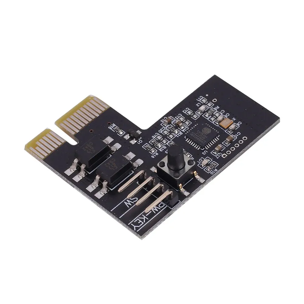
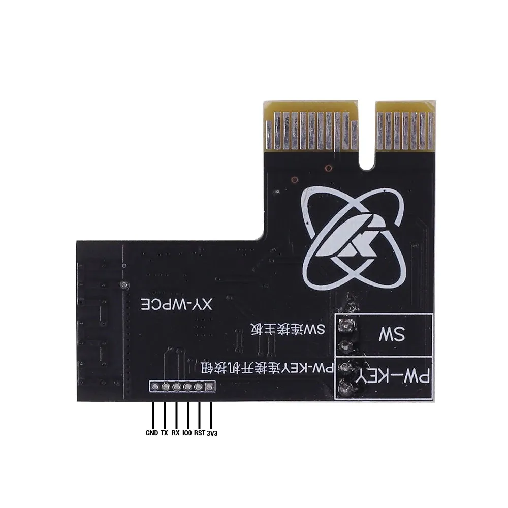
Sinilink PCIe Computer Remote (XY-WPCE)
A simple remote control/monitor device for use with standard PCs.
Essentially a proxy between the power switch and motherboard. Depending on the version, the module may also be wired between the power LED(s) to discern the power status (running/off/sleep) of the PC.
The WPCE version (this device) determines the power status via the normal/aux 3v3 rails on the PCI-Express slot so it
does not feature the power led connections.

Flashing
The module uses 1mm pitch headers which are considerably smaller and fussier to deal with relative to the 2.54mm
pitch headers that are more common.
You don't have to solder wires to program, though.
I was able to strip some solid core cat5 cables; the bare copper wire was precisely the right size to fit inside
of the hole.

| ESP32 Pin | USB Serial Pin | Comments |
|---|---|---|
| 3V3 | 3V3 | Connect to dedicated 3V3 1A power supply if encountering brown out |
| RST | 3V3 | ESP needs the RST/EN pin pulled UP to activate the chip |
| IO0 | Ground | IO0 must be pulled down to enable bootloader mode |
| RX | TX | |
| TX | RX | |
| GND | Ground | If using a dedicated power supply with the USB programmer, make sure that the GND for the programmer and power supply are linked! |
Connect all 6 pins as indicated and then power up the device and then plug in the USB programmer.
The module should immediately enter boot loader mode and should be "discoverable" with esptool.py.
While not strictly necessary, you may wish to backup the flash content before overwriting with ESPHome.
# Confirm that you can "see" the module
❯ esptool.py --port /dev/ttyUSB0 chip_id

# Double check the type/size of the flash chip
❯ esptool.py --port /dev/ttyUSB0 flash_id

# Read out the flash; in this case, the `flash_id` command indicated that the ESP had 2MB of built in flash memory
❯ esptool.py --port /dev/ttyUSB0 read_flash 0x000000 0x200000 flash_backup.bin
GPIO Pinout
| Pin | Function | Notes |
|---|---|---|
| GPIO2 | OUTPUT | Status LED (inverted) |
| GPIO4 | INPUT | Button on module PCB, used by OEM firmware for WiFi config (inverted) |
| GPIO5 | OUTPUT | Wired to PC motherboard, simulates pressing the power button |
| GPIO10 | INPUT | Wired to the PC power button (inverted) |
| GPIO12 | INPUT | Wired to the 3v3 power rail on PCI-Express slot to detect if PC is powered up. (inverted) |
Basic Configuration
The configuration below covers just the basics for getting the various GPIO pins configured / usable in ESPHome.
Depending on your specific needs, more configuration will likely be needed.
E.G.: most motherboards will interpret the power button being pressed for 5+ seconds to mean "shutdown now". Exposing
GPIO5 to Home Assistant directly as a gpio switch may result in the PC powering off a few seconds after it's powered
on.
substitutions:
  friendly_name: "My PC Power Control"
  friendly_name_short: "My PC"

  hostname: "my-pc-power-remote-control"

esphome:
  name: ${hostname}
  # Necessary to prevent relay trigger on ESP restart / wifi loss
  on_boot:
    then:
      - output.turn_off: out_relay

  # Shows up in UI
  comment: "Remote power button for ${friendly_name_short}."

esp8266:
  # Specifically a 'ESP8285H16' with 2MB built in flash
  # See: https://docs.platformio.org/en/stable/boards/espressif8266/esp8285.html
  board: esp8285

logger:
  level: INFO

script:
  - id: regular_press
    mode: single
    then:
      - output.turn_on: out_relay
      - delay: .5s
      - output.turn_off: out_relay

status_led:
  pin:
    number: GPIO02
    inverted: True

binary_sensor:
  - name: "${friendly_name_short} WiFi Config Button"
    platform: gpio
    pin:
      number: GPIO04
      mode: INPUT_PULLUP
      inverted: True

  - name: "${friendly_name_short} Power Status"
    platform: gpio
    id: inp_power_status
    pin:
      number: GPIO12
      mode: INPUT_PULLUP
      inverted: True

  - name: "${friendly_name_short} Case Button"
    platform: gpio
    pin:
      number: GPIO10
      mode: INPUT_PULLUP
      inverted: True

    # To accurately mimic the "button wired directly to motherboard" function, use on_press/on_release
    on_press:
      - output.turn_on: out_relay
    on_release:
      - output.turn_off: out_relay

    # To implement more sophisticated functionality like the "lock out" mode in the OEM firmware
    #   use on_click.
    ##
    on_click:
      then:
        - lambda: |-
            // Implement sophisticated logic here
            id(sw_pc_power).toggle();

switch:
  - name: "${friendly_name_short} Power"
    id: sw_pc_power
    platform: template
    lambda: |-
      if (id(inp_power_status).state) {
        return true;
      } else {
        return false;
      }

    # Mimic the user pressing the button
    turn_on_action:
      - script.execute: regular_press
    turn_off_action:
      - script.execute: regular_press

output:
  - platform: gpio
    id: out_relay
    pin: GPIO5