QIACHIP Smart Switch
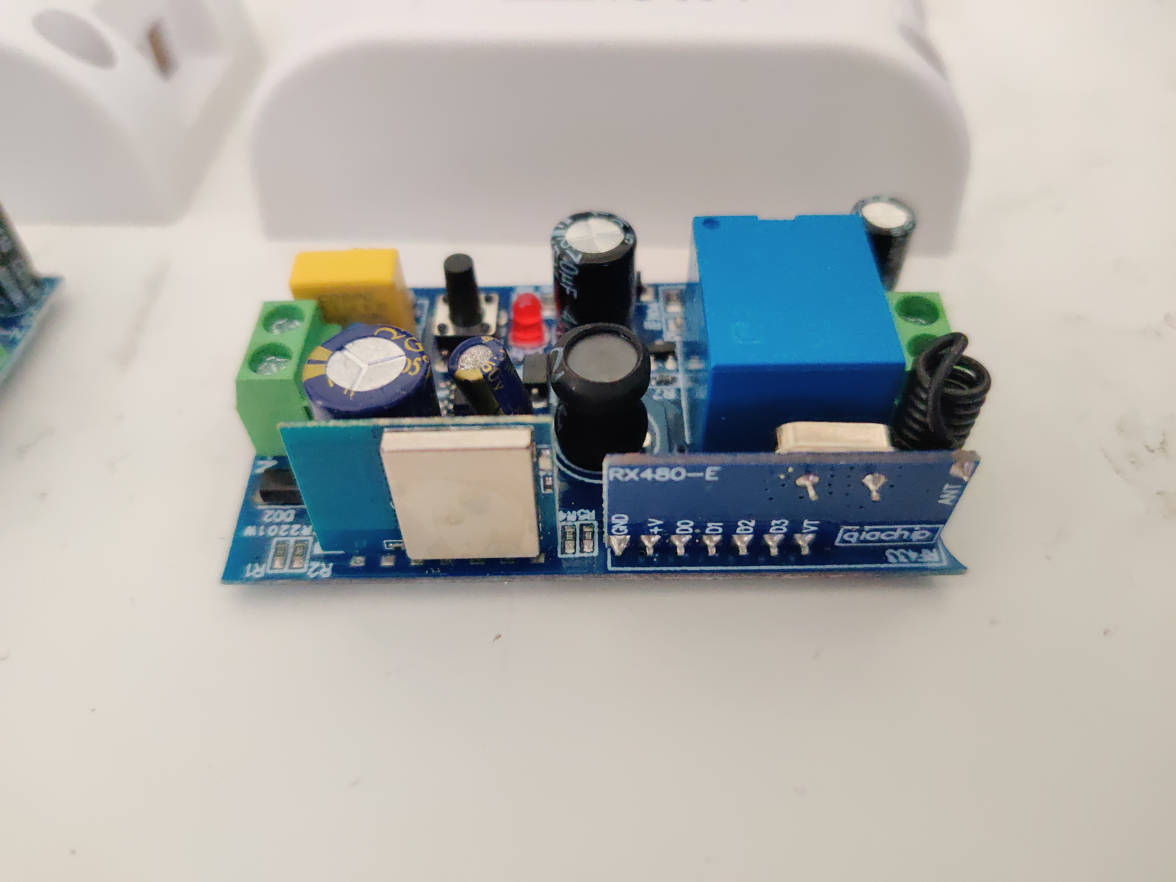
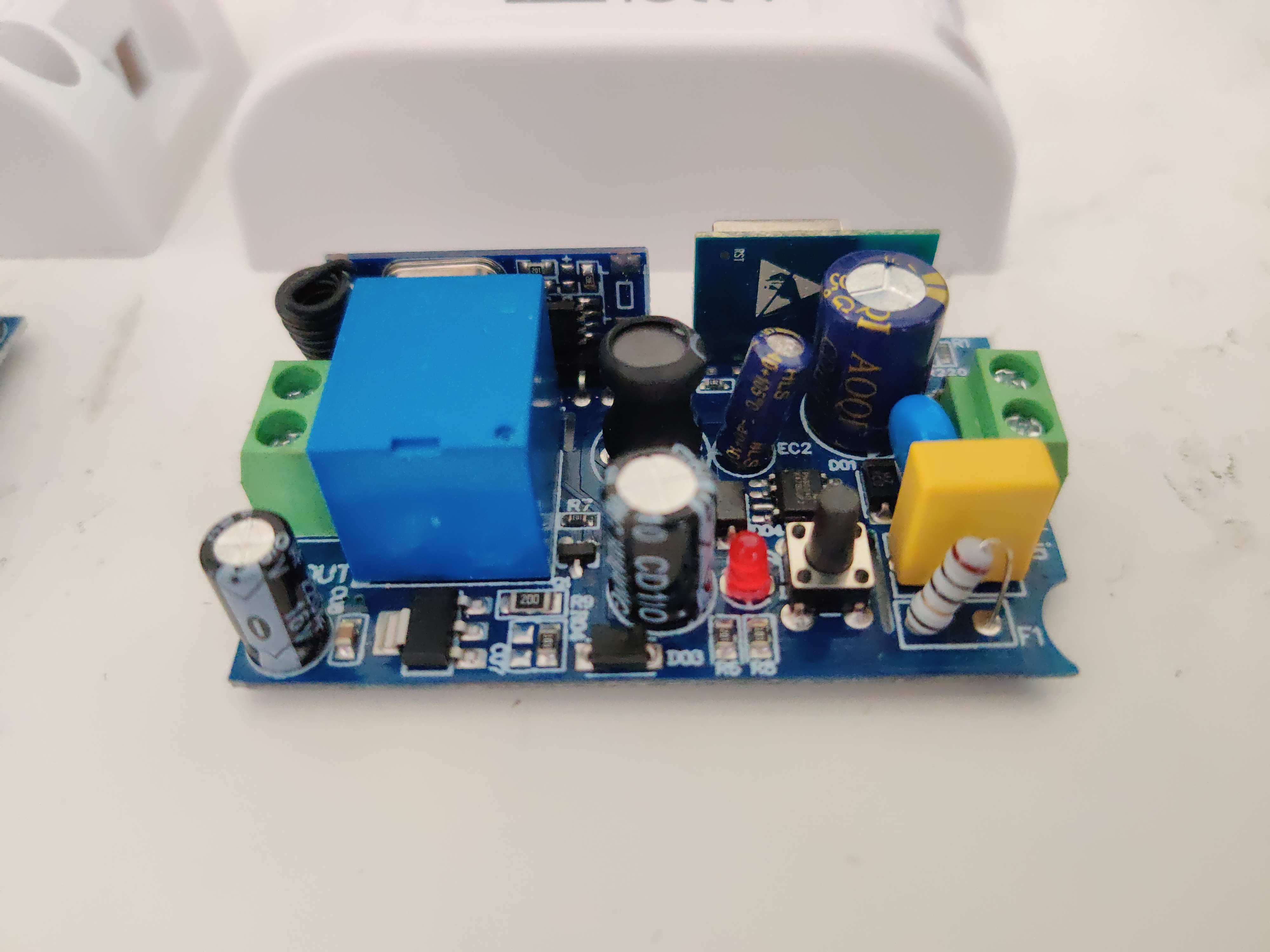
Single channel relay with 433Mhz RF module. On this device, the relay is controlled directly by the RF module, and the ESP module talks to the RF module over UART. For example, when a command to turn on the relay comes in over wifi, this is sent over the UART to the RF module, which then switches the relay. When a 433Mhz control button paired to the module is pressed, the RF module switches the relay and tells the ESP over UART.
Since the RF module still handles all the RF input, the pairing instructions are the same. Press the button on the module a certain amount of times, then press the RF button(s).
- For momentary mode, press the button on the module once, then the RF button.
- For toggle mode ('normal' mode), press the button twice, then the RF button.
- For interlocking mode, press the button three times, then the first RF button, then the second.
- To clear all remotes, press the button eight times.
Because the ESP's main UART is connected to the RF module, programming with an external UART and pulling down GPIO0 does not work, you must use tuya-convert. Since flashing the ESP does not reset the RF module, your paired remotes will not be changed.
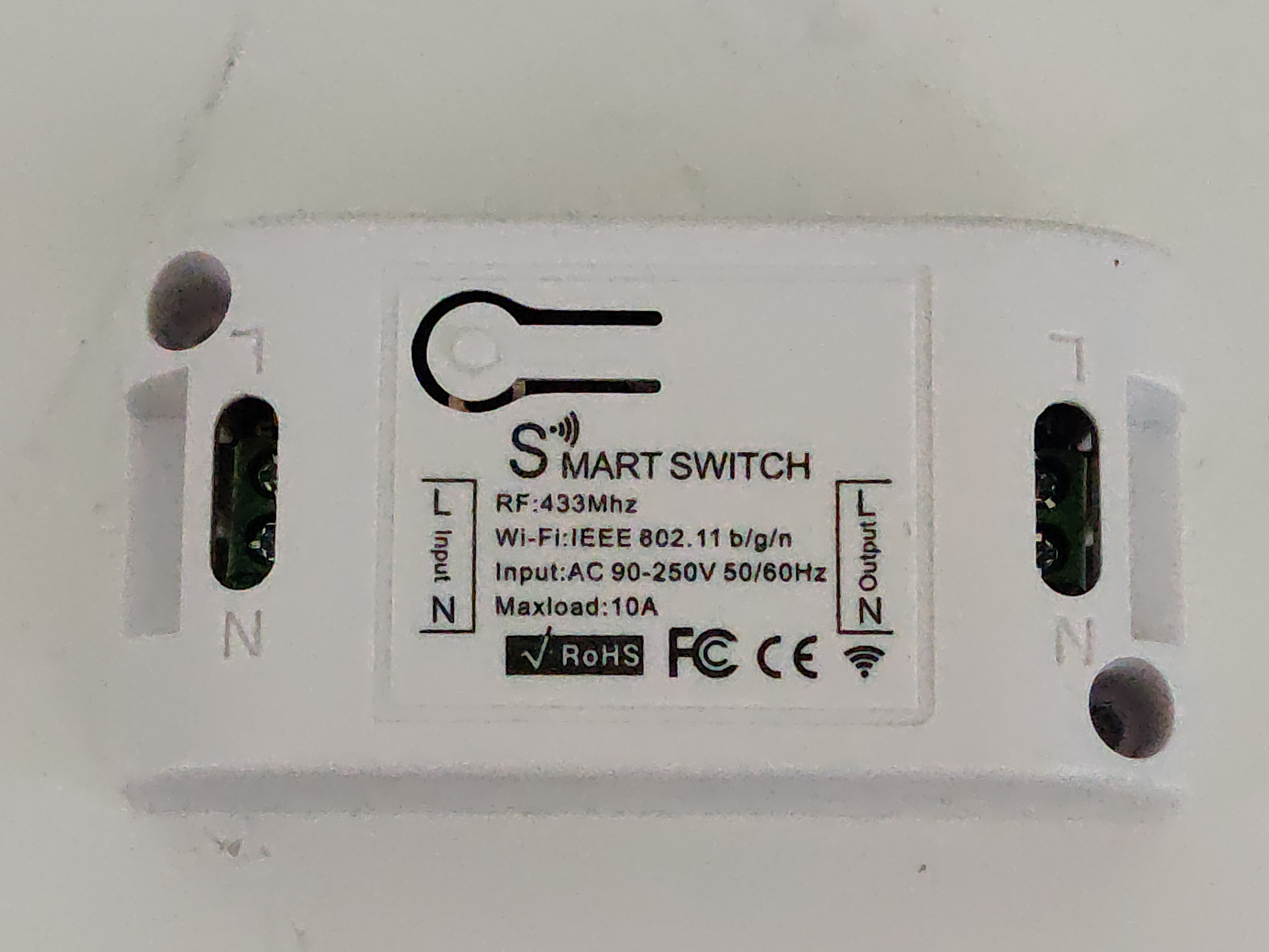
Pictures


GPIO Pinout
| Pin | Function |
|---|---|
| GPIO1 | UART TX |
| GPI03 | UART RX |
| GPIO4 | Blue LED on ESP module |
Basic Configuration
To handle the incoming UART messages from the RF module, a custom module is required. You will need both a yaml file and qiachip-uart.h.
qiachip.yaml:
substitutions:
  device_name: qiachip_test
  friendly_name: QIACHIP Test

esphome:
  name: ${device_name}
  on_boot:
    then:
      - uart.write:
          [
            0x3C,
            0x59,
            0x97,
            0x8E,
            0x03,
            0xFE,
            0x19,
            0x82,
            0x9A,
            0x87,
            0x0C,
            0x87,
            0x16,
            0x87,
            0x82,
            0x86,
            0x7E,
            0x04,
            0x87,
            0x1E,
            0x87,
            0x8E,
            0x86,
            0x3E,
            0x1A,
            0x16,
            0x16,
            0x94,
            0x16,
            0x16,
            0x8F,
            0x87,
            0x02,
            0x4C,
            0x12,
            0x50,
            0x88,
            0x8E,
            0x87,
            0x15,
            0x3A,
            0x86,
            0x82,
            0xFE,
            0x8F,
            0x16,
            0x0F,
            0x07,
            0x09,
            0x9B,
            0xFE,
            0x96,
            0x8B,
            0x96,
            0x1B,
            0x08,
            0x87,
            0x07,
            0x96,
            0x82,
            0xC6,
            0xD5,
            0x0A,
            0xD2,
            0x82,
            0x92,
            0x0E,
            0xFF,
          ]
  includes:
    - qiachip-uart.h

esp8266:
  board: esp01_1m

wifi:
  ssid: !secret wifi_ssid
  password: !secret wifi_password
  fast_connect: on #we only have one WiFi AP so just use the first one that matches
  ap: #since we listed an SSID above, this AP mode will only enable if no WiFi connection could be made
    ssid: ${friendly_name}_AP
    password: !secret wifi_password

logger:
  hardware_uart: UART1 # move logging to UART 1 since RF module is on UART 0
#  baud_rate: 0 #disable UART logging

# Enable Home Assistant API
api:

# Enable OTA updates
ota:
  safe_mode: True

# Enable web server
web_server:
  port: 80

uart:
  baud_rate: 9600
  tx_pin: GPIO1
  rx_pin: GPIO3

#status_led:
#  pin:
#    number: GPIO04
#    inverted: true

binary_sensor:
  - platform: custom
    lambda: |-
      auto qiachip_uart = new QiachipUART();
      App.register_component(qiachip_uart);
      return {qiachip_uart};

    binary_sensors:
      name: "RFModule"
      on_press:
        switch.turn_on: relay
      on_release:
        switch.turn_off: relay
      internal: true

switch:
  - platform: gpio
    name: "${friendly_name}"
    id: "relay"

    pin: GPIO4 # using ESP module LED
    inverted: true
    on_turn_on:
      - uart.write: [0xAC, 0x28, 0x00, 0x21]
    on_turn_off:
      - uart.write: [0xAC, 0x20, 0x00, 0x29]
The UART module checks the UART buffer every 100ms, expecting the 4 byte long messages sent by the RF module, and updates when it receives one.
qiachip-uart.h:
#include "esphome.h"

class QiachipUART : public PollingComponent, public BinarySensor{
 public:
  QiachipUART() : PollingComponent(100) {}

  void setup() override {
  }
  void update() override {
    if (Serial.available() == 4) {
      char buffer[4];
      Serial.readBytes(buffer, 4);
      if (buffer[3] == 0xF7) {
        // 53 00 01 F7
        publish_state(true);
      } else if (buffer[3] == 0xF6) {
        // 53 00 00 F6
        publish_state(false);
      }
    } else if (Serial.available() > 4) {
      while (Serial.available()) {
        Serial.read();
      }
    }
  }
};
Split Configuration
If you have multiple of these relays, you may want to keep the shared code in one file and only put device specific information in files for each relay. Leave qiachip-uart.h as is in this situation.
qiachip-common.yaml:
esphome:
  name: ${device_name}
  on_boot:
    then:
      - uart.write:
          [
            0x3C,
            0x59,
            0x97,
            0x8E,
            0x03,
            0xFE,
            0x19,
            0x82,
            0x9A,
            0x87,
            0x0C,
            0x87,
            0x16,
            0x87,
            0x82,
            0x86,
            0x7E,
            0x04,
            0x87,
            0x1E,
            0x87,
            0x8E,
            0x86,
            0x3E,
            0x1A,
            0x16,
            0x16,
            0x94,
            0x16,
            0x16,
            0x8F,
            0x87,
            0x02,
            0x4C,
            0x12,
            0x50,
            0x88,
            0x8E,
            0x87,
            0x15,
            0x3A,
            0x86,
            0x82,
            0xFE,
            0x8F,
            0x16,
            0x0F,
            0x07,
            0x09,
            0x9B,
            0xFE,
            0x96,
            0x8B,
            0x96,
            0x1B,
            0x08,
            0x87,
            0x07,
            0x96,
            0x82,
            0xC6,
            0xD5,
            0x0A,
            0xD2,
            0x82,
            0x92,
            0x0E,
            0xFF,
          ]
  includes:
    - qiachip-uart.h

esp8266:
  board: esp01_1m

wifi:
  ssid: !secret wifi_ssid
  password: !secret wifi_password
  fast_connect: on #we only have one WiFi AP so just use the first one that matches
  ap: #since we listed an SSID above, this AP mode will only enable if no WiFi connection could be made
    ssid: ${friendly_name}_AP
    password: !secret wifi_password

logger:
  hardware_uart: UART1 # move logging to UART 1 since RF module is on UART 0
#  baud_rate: 0 #disable UART logging

# Enable Home Assistant API
api:

# Enable OTA updates
ota:
  safe_mode: True

# Enable web server
web_server:
  port: 80

uart:
  baud_rate: 9600
  tx_pin: GPIO1
  rx_pin: GPIO3

#status_led:
#  pin:
#    number: GPIO04
#    inverted: true

binary_sensor:
  - platform: custom
    lambda: |-
      auto qiachip_uart = new QiachipUART();
      App.register_component(qiachip_uart);
      return {qiachip_uart};

    binary_sensors:
      name: "RFModule"
      on_press:
        switch.turn_on: relay
      on_release:
        switch.turn_off: relay
      internal: true

switch:
  - platform: gpio
    name: "${friendly_name}"
    id: "relay"

    pin: GPIO4 # using ESP module LED
    inverted: true
    on_turn_on:
      - uart.write: [0xAC, 0x28, 0x00, 0x21]
    on_turn_off:
      - uart.write: [0xAC, 0x20, 0x00, 0x29]
And for each device's yaml:
substitutions:
  device_name: qiachip
  friendly_name: QIACHIP Relay

<<: !include qiachip-common.yaml