Aoycocr X13 Outdoor Plug (2AKBP-X13)
All information provided is from Iprak documentation.
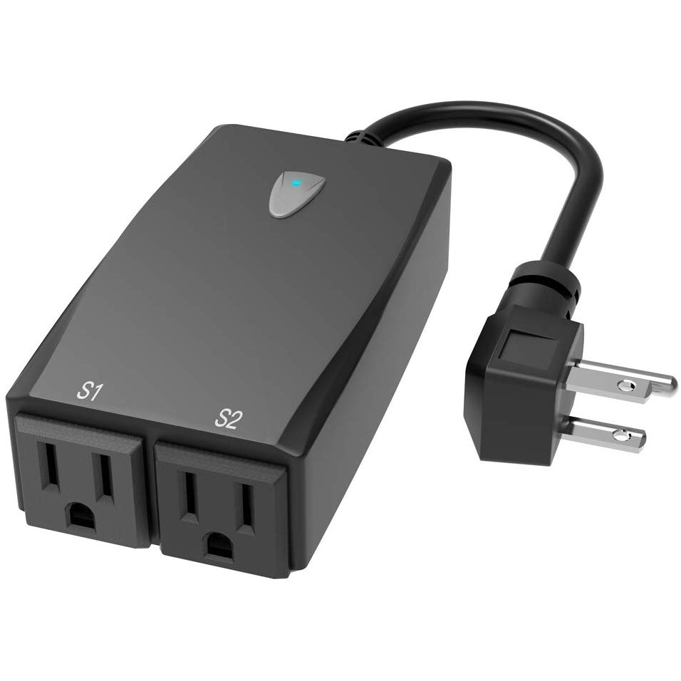
The device has 2 indicator LEDs under the button and 2 indiviually controllable outlets. FCC filing Tasmato wiki mentioned that it might not be able to use Tuya-Convert.
Product Image
GPIO Pinout
The GPIO pinout was learned from Iprak documentation. The ESP module is ESP8266-S3 and the FCC filing provided the pins
- EN
- TOUT
- GPIO12
- GPIO14
- GPIO13
- GPIO15
- GPIO0
- GPIO2
- GPIO4
- GPIO 5
- RX
- TX
- VCC
- GND
The pins are on alternate sides:
1  3  5  7  9  11  13
2  4  6  8  10 12  14
The GPIOs being used are:
- LED#1:GPIO0, inverted
- LED#2:GPIO2, inverted
- Button:GPIO13
- Relay1:GPIO15
- Relay2:GPIO12
Basic Configuration
The below YAML template is from Iprak documentation.
substitutions:
  devicename: aoycocr_x13
  proper_devicename: Aoycocr X13

esphome:
  name: $devicename

esp8266:
  board: esp01_1m
  arduino_version: [email protected]

wifi:
  ssid: !secret wifi_ssid
  password: !secret wifi_password
  ap:


captive_portal:
logger:
api:
ota:

# https://tasmota.github.io/docs/Components/
# https://templates.blakadder.com/aoycocr_X13.html

binary_sensor:
  - platform: gpio
    pin:
      number: GPIO13
    id: button
    on_press:
     - switch.toggle: relay1
     - switch.toggle: relay2

  - platform: status
    name: $devicename

switch:
  - platform: gpio
    name: "$devicename 1"
    pin: GPIO15
    id: relay1
    icon: "mdi:floor-lamp"
    #Led2 represents switch 1
    on_turn_on:
      - output.turn_on: led2
    on_turn_off:
      - output.turn_off: led2

  - platform: gpio
    name: "$devicename 2"
    pin: GPIO12
    id: relay2
    icon: "mdi:floor-lamp"

output:
  - platform: gpio
    pin: GPIO0
    id: led2
    inverted: yes

status_led:
  pin:
    number: GPIO2
    inverted: yes