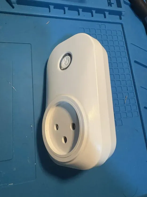
Tuya Smart Plug 16A IL
General Notes
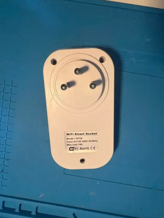
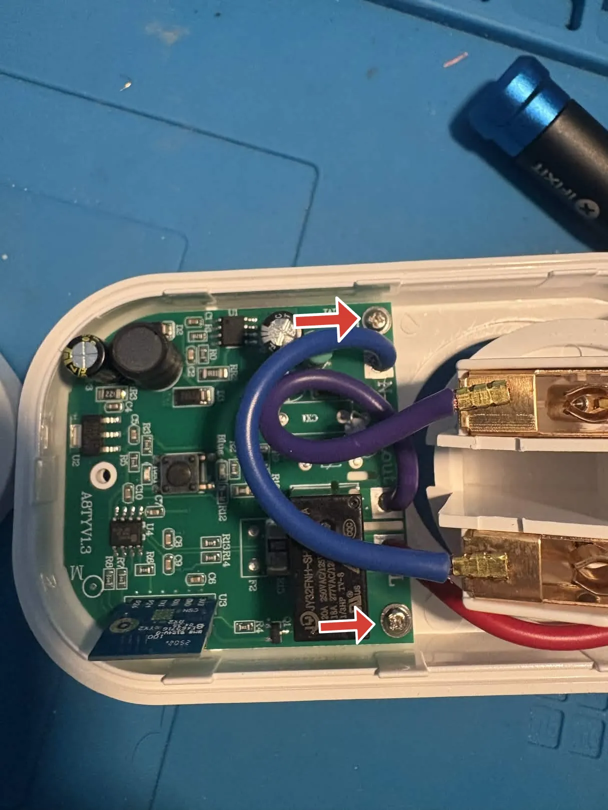
While a specific model number was not specified on the exterior, a8tyv1.3 is written on the board inside.
These plugs are available in various models, with or without energy monitoring and USB ports.
The 16A smart plug with energy monitor is not flashable using tuya-cloudcutter. The main module version shown in the Smart Life app is V1.1.23, which is on the known patched firmware list.
Some disassembly and soldering is required in order to flash the device via UART.
Two Wi-Fi module variants have been observed on this main PCB: a CB2S / BK72xx variant and a WB02A / LN882H variant. Check which module is installed before choosing the ESPHome platform and GPIO mapping.
Product Images
Disassembly and Flashing
There are three external Phillips screws that must be removed to open the device (see image above). Additionally, two internal screws secure the board to the plastic casing and must also be removed.
The Wi-Fi module pins are exposed on the underside of the board and are clearly labeled. These are correct for both variants; the main PCB seems to be identical up to part assembly options.
CB2S / BK72xx variant
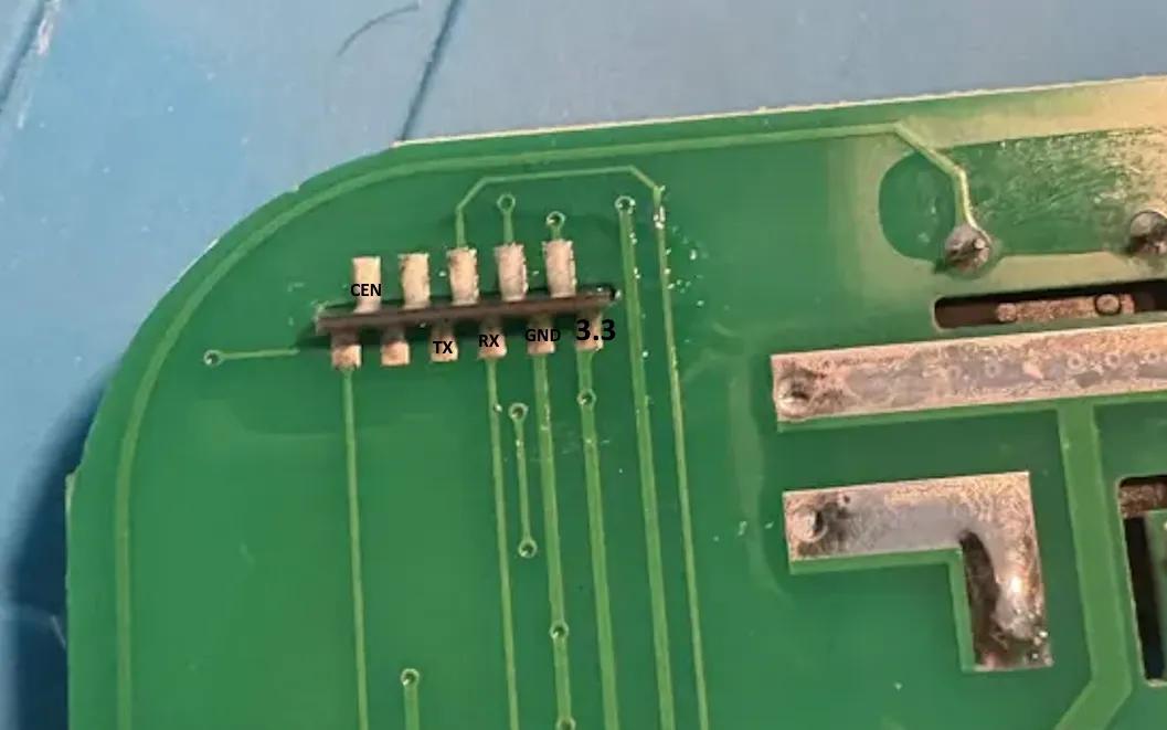
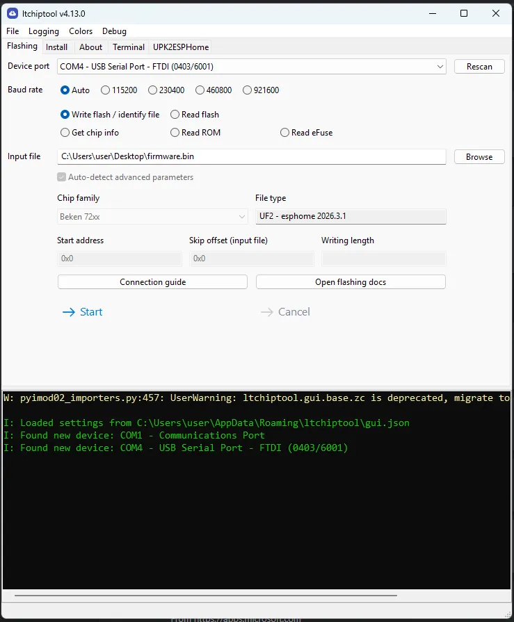
Connect the pins to a UART TTL adapter, then hold the CEN pin to GND for a few seconds while
flashing the ESPHome firmware using ltchiptool.
WB02A / LN882H variant
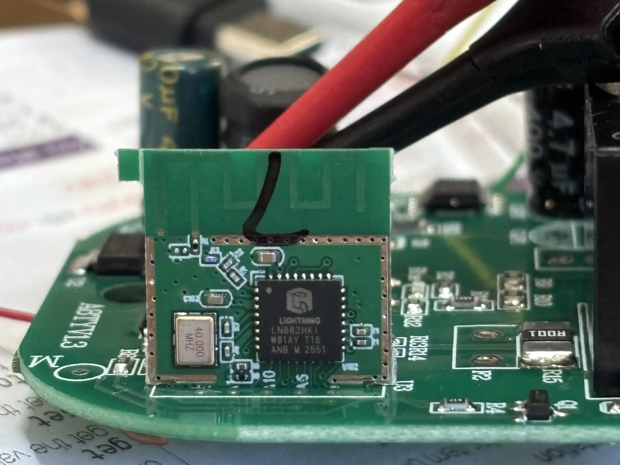
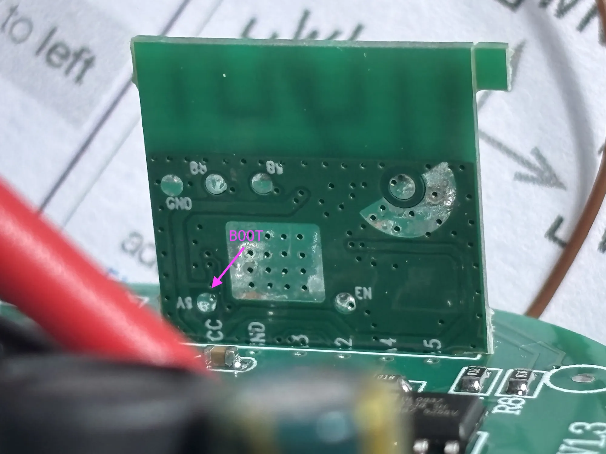
Connect the pins to a USB-to-UART adapter. The PA09/BOOT pin needs to be continuously pulled down to GND while flashing.
The PA09 pin is accessible via a test pad on the back of the module (see picture). The device consumes about 100mA
(@ 3.3V) while booted normally and about 70mA when in download mode. When flashing is done, release PA09 and reset
using CEN. More details in the LibreTiny docs.
If the module reports a blank/all-FF Tuya OTP MAC, use the on_boot MAC workaround shown in the WB02A configuration
below to assign a stable MAC based on the ESPHome node name.
GPIO Pinout
| CB2S | WB02A | Function |
|---|---|---|
| P6 | PA07 | CF1 pin |
| P7 | PA06 | CF pin |
| P8 | PA10 | Blue LED |
| P10 | PA03 | Switch button |
| P24 | PA04 | SEL pin |
| P26 | PA05 | Relay + Red LED |
Basic configuration - CB2S / BK72xx variant
# Basic Configsubstitutions:  friendly_name: Socket 16A IL  device_name: socket-16a-il
esphome:  name: ${device_name}  friendly_name: ${friendly_name}
bk72xx:  board: cb2s
# Enable logginglogger:
wifi:  # Enable fallback hotspot (captive portal) in case wifi connection fails  ap:
output:  - platform: gpio    id: button_led    pin: P8    inverted: true
binary_sensor:  - platform: gpio    id: binary_switch    pin:      number: P10      inverted: true      mode: INPUT_PULLUP    on_press:      then:        - switch.toggle: relay
switch:  - platform: gpio    name: Relay Switch    id: relay    restore_mode: "RESTORE_DEFAULT_OFF"    pin: P26    on_turn_on:      then:        - output.turn_on: button_led    on_turn_off:      then:        - output.turn_off: button_led
sensor:  - platform: hlw8012    model: BL0937    cf_pin:      number: P7      inverted: true    cf1_pin:      number: P6      inverted: true    sel_pin:      number: P24      inverted: true    current:      name: Current      filters:        - multiply: 0.5    voltage:      name: Voltage    power:      name: Power    energy:      name: Energy    voltage_divider: 800    current_resistor: 0.001 ohm    update_interval: 1s    change_mode_every: 1
Basic configuration - WB02A / LN882H variant
# Basic Configsubstitutions:  friendly_name: Socket 16A IL  device_name: socket-16a-il
esphome:  name: ${device_name}  friendly_name: ${friendly_name}  # Some WB02A/LN882H units have a blank/all-FF Tuya OTP MAC.  # Generate a stable MAC from the ESPHome node name.  on_boot:    priority: 800    then:      - lambda: |-          const char *name = App.get_name().c_str();
          uint32_t hash = 2166136261u;          while (*name) {            hash ^= (uint8_t) *name++;            hash *= 16777619u;          }
          uint8_t mac[6] = {            0x02,  // locally administered, unicast            0xA0,            0xB0,            (uint8_t) (hash >> 16),            (uint8_t) (hash >> 8),            (uint8_t) hash          };
          WiFi.setMacAddress(mac);
ln882x:  board: generic-ln882hki
# Enable logginglogger:
wifi:  # Enable fallback hotspot (captive portal) in case wifi connection fails  ap:
output:  - platform: gpio    id: button_led    pin: PA10    inverted: true
binary_sensor:  - platform: gpio    id: binary_switch    pin:      number: PA03      inverted: true      mode: INPUT_PULLUP    on_press:      then:        - switch.toggle: relay
switch:  - platform: gpio    name: Relay Switch    id: relay    restore_mode: RESTORE_DEFAULT_OFF    pin: PA05    on_turn_on:      then:        - output.turn_on: button_led    on_turn_off:      then:        - output.turn_off: button_led
sensor:  - platform: hlw8012    model: BL0937    cf_pin:      number: PA06      inverted: true    cf1_pin:      number: PA07      inverted: true    sel_pin:      number: PA04      inverted: true    current:      name: Current      accuracy_decimals: 3    voltage:      name: Voltage    power:      name: Power    energy:      name: Energy    voltage_divider: 1600    current_resistor: 0.001 ohm    update_interval: 1s    change_mode_every: 1
Additional notes
This guide was based on the WHDZO3 guide and adapted to this board.