
KinCony-B2 (ESP32-S3 2CH Relay board)
Device Type:
Electrical Standard:
Board:
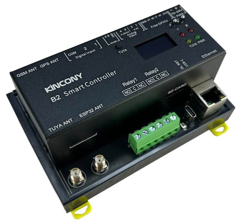
Resources
ESPHome Configuration
The basic configuration contains the KinCony B2 ESP32-S3 relay board’s hardware definitions and core ESPHome components.
esphome:  name: b2  friendly_name: b2
esp32:  board: esp32-s3-devkitc-1  framework:    type: arduino
# Enable logginglogger:  hardware_uart: USB_SERIAL_JTAG
ethernet:  type: W5500  clk_pin: GPIO1  mosi_pin: GPIO2  miso_pin: GPIO41  cs_pin: GPIO42  interrupt_pin: GPIO43  reset_pin: GPIO44
i2c:  - id: bus_a    sda: 8    scl: 18    scan: true    frequency: 400kHz
uart:  - id: uart_1 # RS485    baud_rate: 9600    debug:      direction: BOTH      dummy_receiver: true      after:        timeout: 10ms    tx_pin: 38    rx_pin: 39
switch:  - platform: uart    uart_id: uart_1    name: "RS485 Button"    data: [0x11, 0x22, 0x33, 0x44, 0x55]
  - platform: gpio    name: "b2-output01"    pin: 4    inverted: false
  - platform: gpio    name: "b2-output02"    pin: 46    inverted: false
binary_sensor:  - platform: gpio    name: "b2-input01"    pin:      number: 6      inverted: true
  - platform: gpio    name: "b2-input02"    pin:      number: 7      inverted: true
  # Pull-up resistors on PCB  - platform: gpio    name: "b2-W1-io47"    pin:      number: 47      inverted: true
  - platform: gpio    name: "b2-W1-io48"    pin:      number: 48      inverted: true
  - platform: gpio    name: "b2-W1-io17"    pin:      number: 17      inverted: true
  - platform: gpio    name: "b2-W1-io40"    pin:      number: 40      inverted: true
ads1115:  - address: 0x48
sensor:  - platform: ads1115    multiplexer: "A0_GND"    gain: 6.144    resolution: 16_BITS    name: "ADS1115 Channel A0-GND"    update_interval: 5s  - platform: ads1115    multiplexer: "A1_GND"    gain: 6.144    name: "ADS1115 Channel A1-GND"    update_interval: 5s  - platform: ads1115    multiplexer: "A2_GND"    gain: 6.144    name: "ADS1115 Channel A2-GND"    update_interval: 5s  - platform: ads1115    multiplexer: "A3_GND"    gain: 6.144    name: "ADS1115 Channel A3-GND"    update_interval: 5s
Advanced Configuration
This configuration adds the onboard SSD1306 display example from the vendor configuration.
esphome:  name: b2  friendly_name: b2
esp32:  board: esp32-s3-devkitc-1  framework:    type: arduino
# Enable logginglogger:  hardware_uart: USB_SERIAL_JTAG
# Enable Home Assistant APIapi:
ethernet:  type: W5500  clk_pin: GPIO1  mosi_pin: GPIO2  miso_pin: GPIO41  cs_pin: GPIO42  interrupt_pin: GPIO43  reset_pin: GPIO44
i2c:  - id: bus_a    sda: 8    scl: 18    scan: true    frequency: 400kHz
uart:  - id: uart_1 # RS485    baud_rate: 9600    debug:      direction: BOTH      dummy_receiver: true      after:        timeout: 10ms    tx_pin: 38    rx_pin: 39
switch:  - platform: uart    uart_id: uart_1    name: "RS485 Button"    data: [0x11, 0x22, 0x33, 0x44, 0x55]
  - platform: gpio    name: "b2-output01"    pin: 4    inverted: false
  - platform: gpio    name: "b2-output02"    pin: 46    inverted: false
binary_sensor:  - platform: gpio    name: "b2-input01"    pin:      number: 6      inverted: true
  - platform: gpio    name: "b2-input02"    pin:      number: 7      inverted: true
  # Pull-up resistors on PCB  - platform: gpio    name: "b2-W1-io47"    pin:      number: 47      inverted: true
  - platform: gpio    name: "b2-W1-io48"    pin:      number: 48      inverted: true
  - platform: gpio    name: "b2-W1-io17"    pin:      number: 17      inverted: true
  - platform: gpio    name: "b2-W1-io40"    pin:      number: 40      inverted: true
ads1115:  - address: 0x48
sensor:  - platform: ads1115    multiplexer: "A0_GND"    gain: 6.144    resolution: 16_BITS    name: "ADS1115 Channel A0-GND"    update_interval: 5s  - platform: ads1115    multiplexer: "A1_GND"    gain: 6.144    name: "ADS1115 Channel A1-GND"    update_interval: 5s  - platform: ads1115    multiplexer: "A2_GND"    gain: 6.144    name: "ADS1115 Channel A2-GND"    update_interval: 5s  - platform: ads1115    multiplexer: "A3_GND"    gain: 6.144    name: "ADS1115 Channel A3-GND"    update_interval: 5s
font:  - file: "gfonts://Roboto"    id: roboto    size: 20
display:  - platform: ssd1306_i2c    i2c_id: bus_a    model: "SSD1306 128x64"    address: 0x3C    lambda: |-      it.printf(0, 0, id(roboto), "KinCony B2");